Yet more carbon fibre
For reasons of it being fun, if somewhat stressful, to design, build, and then trust things I wanted to build new mast spreaders for Aquabelle. Another reason is that the old one are worn, one is bent, and they have starting signs of being used for long enough – the anodisation of the aluminum has micro cracks att the mast attachment end. The spreaders will be built in carbon fibre and then some protective layer of glass and linnen fibre, both to electrically isolate the metal parts from the carbon fibre and also to protect the carbon fibre from UV and outer skin damage.
Some math
In the work with the inner forestay I estimated the maximum righting moment RM_30 to be about 28 kNm. Since this will be a more expensive problem if the part fails (the mast will fall down) compared to the inner forestay, I will double check this with some more numbers. Once again I will use the equations in Principles of Yacht Design by Larsson, Eliasson, Orych (Fourth edition).
Starting at Fig. 11.4 the rig is of type F-1, a fractional rig with one pair of mast spreaders. The worst case is when all of the righting moment is taken up by the top shroud. Furthermore, to get maximum force, I will use the 12 m jib halyard height as the height instead of from the water. I will now go through all the equations with the correct number so that a final equation for the shroud dimensioned load is calculated.
Fig 11.4 and 11.3, F2 = RM [kNm] / 12 m = RM/12 kN transversal load at the shroud attachment in the mast.
Fig 11.6 D2 = F2/ sin(b) kN, where D2 is the shroud load and b is the angle between the shroud and the mast.
This gives: D2 = RM/( 12 * sin(b) ) kN.
b can be approximated by knowing tangens trigonometrics, the spreader length and the distance between the spreader attachment and the shroud attachment. The spreader is 1 meter and the distance between the attachment points mentioned is 5.5 meters. This gives an angle of b = 10.3 degrees, which in turn gives:
D2 = RM / (12 * 0.17889) kN = RM/ 2.1467 kN
The dimensioned load for the shroud is simply 3 times this as specified in Fig 11.6. Let’s double check the 28 kNm from the inner forestay calculations:
28 / 2.1467 * 3 = 39.13 kN.
This seems to agree very much with the expected breaking strength of 7mm wire of some 40 kN. For the spreader dimensioning I will use the highest number I have found which is 4300 kg => 42,22 kN which in turn will give dimensioned load on the shroud to D2 = 14,01 kN.
For the spreader dimensioned second moment of inertia is used:
Fig 11.13, I = 0.8 * C1 kN * S^2 m^2 / (E cos(d))
With S being the spreader length 1 m and the angle d guesstimeasured to about 20 degrees, this simplifies to:
I = 0.8 / 0.94 * C1/E
C can be found in the calculation in Fig 11.6:
C1 = F2 – V1*sin(gamma), which when setting gamma to 0 (to get a worse case) simply becomes F2 which we determined to F2 = RM/12 = 28/12 = 2.3 kN.
I is now fully simplified to:
I = 0.851 * 2.3 kNm^2 / E = 1.96 kNm^2 /E = { E = 180 GPa } = 10889 mm4
With unidirectional carbon fibre which has a modulus of elasticity of 180 GPa, this gives (with some unit trickery) 10889 mm4 as the required second moment of inertia.
Fig 11.13 also gives requirements for the spreader Section Modulus close to the mast of:
Fig 11.13, SM = k * S * V * cos (d) = 0.16/sigma * 1000 mm * 14.01 kN * 0.9397 = 2106 / sigma kNmm, where sigma is the yield strength.
I will presume the yield strength is compressive since carbon fibre is much weaker in compression compared to tensile. I will use about 30% of tensile strength. The carbon I have ordered has a breaking strength of 4137 MPa which then gives about 1240 MPa as compressive strength. 1240 MPa = 1,24 kN/mm2
SM = 2106 kNmm / 1.24 kN/mm2 = 1700 mm3.
Furthermore there are requirements on the moment that the spreader attachment needs to be able to absorb:
Fig 11.13, M = 0.16 * 1m * 14.01 kN * cos(d) = 0.16 * 14.01 * 0.9397 kNm = 2.104 kNm, ( about 200 kgm)
To sum it up. We have three types of requirements on the spreader.
Second moments of inertia >= 10889 mm4
Section modulus close to the mast of >= 1700 mm3
Be able to tolerate a Moment in the attachment of >= 2.104 kNm
Click to download an libre office calc sheet to try out the calculations yourself
That's good, so what is up with the old spreaders?
To aid in the calculations of all of the previous and also to analyse the old ones I hacked together some simple Paint-Python based CAD. The required second moment of inertia on aluminum comes out to 28485 mm4 while I have calculated the actual on the profile to 19506 mm4, so either there is something wrong with my code or the old profiles are a bit under specification. Code is supplied at the bottom of the page. The spreader is about 3 mm thick in edge, so to say.

Section modulus can be calculated by taking the second moment of inertia and dividing it by the extreme most point on the geometry compared to the neutral axis to see that the edge is not overloaded. For aluminum the smallest value to to use for sigma is 210 N/mm2. This gives SM requirements for the old spreaders to 2104 kNmm / 210 N * mm2 = 2104/210 [kNmm / N * mm2] = 10000 mm3.
In the critical axis (spreaders are somewhat flat) the extreme point compared to the neutral axis is 12 mm. 19506/12 is not more than 10000 mm3 so there is something I probably do not understand or something wrong with my calculations. The other axis has second moment of intertia of about 244 000 mm4 and a distance of 34 mm => 244 000 / 34 = 7176 mm3.
The old design has not been strong enough in moment since they are worn out (over 25 years sailing mind you) and since the calculations here are alot more difficult (and perhaps require FEM with CAD) I will not delve into that topic for the old spreaders.
New profile design
After some initial design trials with different thicknesses of carbon fibre roughly following the old outline since they need to fit in the same attachments, I have concluded that a 2 mm perimeter with some added thickness of 1 mm on the thickest part where it matters the most for stiffness, will land in the ballpark of second moments of inertia for the old spreaders. Even if the calculation is slightly wrong, the same algorithm is used for a very similar shape, and the requirement is about 3 times less for carbon fibre compared to aluminum.
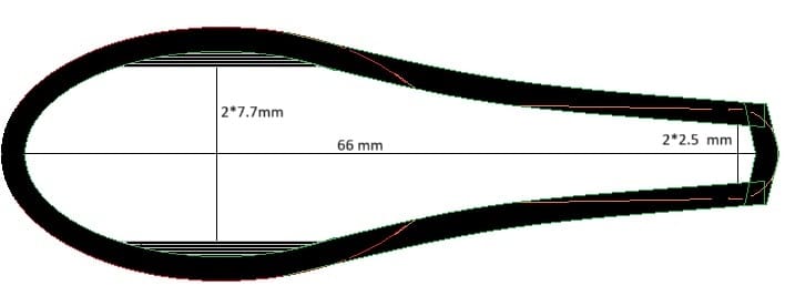
The second moment of inertia for this shape is according to my calculations 19579 mm4, very close to the aluminum one. It is a bit less stiff in the other axis, 158000 compared to 244000 but still, it is the strong axis. The section modulus is because of the similar shape almost the same at 19579/12 = 1631.6 mm3 which almost clears the calculated mark. The problematic part with directional strength when making holes in a material, will require a lot of reinforcement in the hole area stretching out into the spreader. I think this will solve the moment requirement when building. I plan on making solid laminate around the required holes to attach it to the mast. The calculations are really tricky so this will be a verification test, remember 200 kgm kind of means that two adults shall be able to hang from the spreader, which we can do quite easily.
But let’s do some math anyway. Consider the weak axis and only the thick part. If there is a bolt here. Pivot the moment around the bottom. This gives a lever of 0.025 m. 2.104 kNm / 0.0025 m = 420.8 kN. Distributed evenly accross the bolt which is 8 mm and the material is let’s say 3 mm, this gives a pressure of 420.8 kN / 24 mm2 = 17.5 GPa. I guess this will require some substantial reinforcement and maybe I have misunderstood the moment direction, which is also supported due to the fact that spreaders normally can move somewhat up and down on the shroud.
If the moment is taken around the strong axis instead. Numbers become: lever approxmiate 25mm between the holes – 2.104/25 = 8.416 kN in a hole. We can now double the area -> 48 mm2 which in turn gives the pressure 8.416/48 = 0.1753 kN/mm2 = 174 MPa which is about right for aluminum and well within reach for carbon fibre. The trick with fibre construction, as previously mentioned, is being able to transfer that load properly.
All in all, the proposed design is geometrically very similar to Aluminium but Carbon fibre being 2 times to 25 times the compressive strength and twice as stiff this should be ok. The epoxy alone is compareable to high-strength aluminum alloys in compressive strength, but it is a bit elastic.
Layup scheme and build plan
Each layer of carbon fibre adds about 0.25 mm thickness in a vacuum press according to specs for 200 g/m2. which will mean that 1mm will require about 800 g/mm2. To reach 2 mm nominal thickness will require 1600 g/m2. The UD I have ordered is 300 g/m2, which will mean that 6 layers will reach 1800 g/m2. For the thicker part another 1.5 mm is required which means 5 layers more. The trick here is likely to make sufficiently narrow pieces which will be hard.
Each spreader will be built in two halves on top of shaped foam. To transfer loads, take up some torsion and to keep things in place biaxial and woven material will be incorporated. It is only close to the attachment there exists an actual size requirement, hence the middle of the spreaders can probably be a bit thicker to account for the added material.
Final plan:
- Shape halves to the desired shape. Narrow close to attachment to allow more fibers in different directions.
- First lamination: Woven mat, then all layers of UD (5 narrow + 6 full width). Between every other UD layer except the first extra ones, woven at different angles.
- Fill in the end cap as well as the mast end with solid laminate to take up shroud and mast attachment forces.
- Sand and fix up mess after first layers. Glue the two spreaders together. Add nuts into the end caps for shroud attachment.
- Make sure the spreaders fit in the mast attachments.
- Two layers of biaxial sock over each spreader to keep the two halves together.
- Drill holes for glas fibre tube to hold rigging bolts for mast attachments. Add tube.
- Finish end cap for shroud attachment.
- Add finish layer of linen fibre to make them look nice and protect the carbon fibre. Might be glass fibre around to hole to be able to see carbon underneath.
- Other nice things like flag line loops.
- Clear coat.
- DONE!
The build begins - the picture heavy part
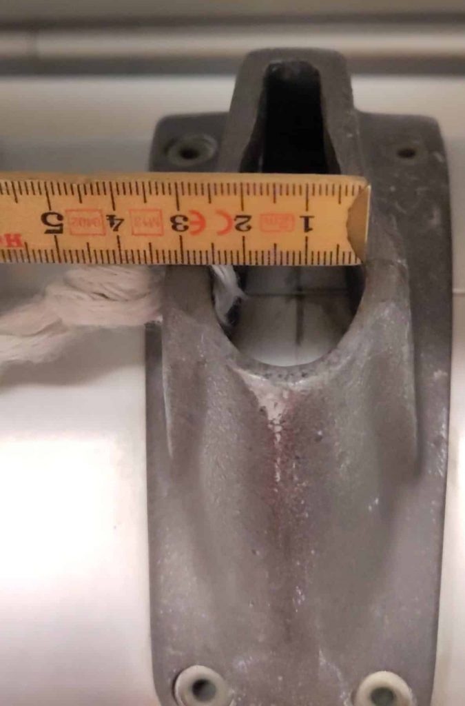
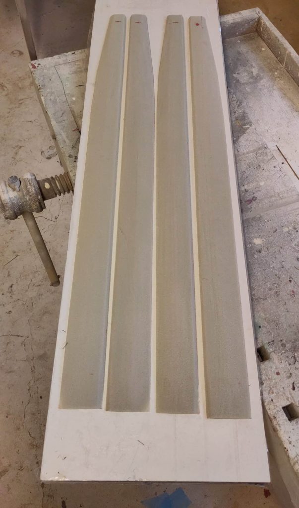
I started by control measuring the current mast attachment before I began so that I wouldn’t do anything stupid. From these measurements I made a template for the foam core. Then the shaping began. I had a really rough sand-paper so the foam went away really quickly. When I felt ready I started cutting all the layers of carbon fibre that was going to be used.
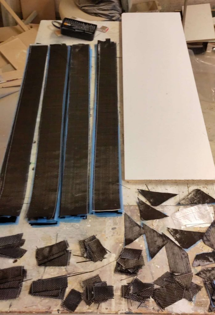
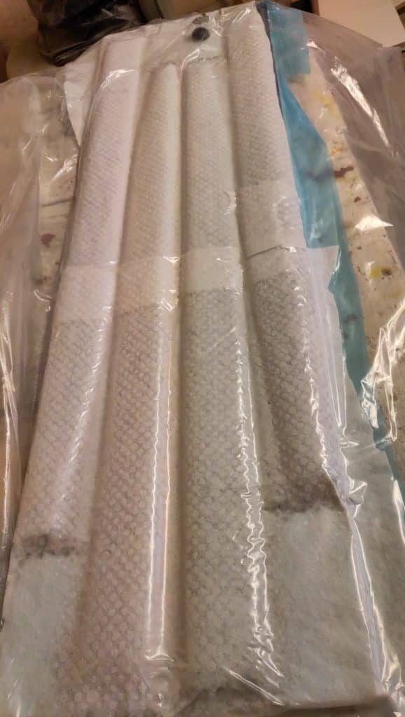
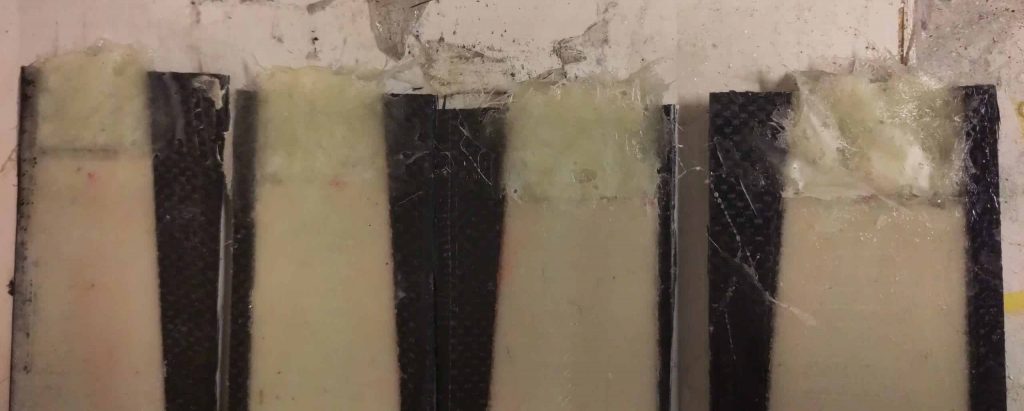

Unfortunatly, due to the messiness of epoxy and the relative time-pressure I do not have any pictures of the 3 hours of straight up laminating. I knew that this would take a long time so I had chosen an epoxy with a gel time of about 2,5 hours, plenty of time. I vacuumed packed the whole thing in one package, but I didn’t manage to get all of the leaks so I ran down and started the vacuum pump every 40 min for the entire evening for 5-10 min. I am not fully aware what I am doing wrong but I think it turned out ok anyway.
The next day I unpacked, but because of the long curing time of the epoxy, about 22 hours, I didn’t dare touch them much more, they still felt slightly soft. I therefore waited to continue the weekend after.
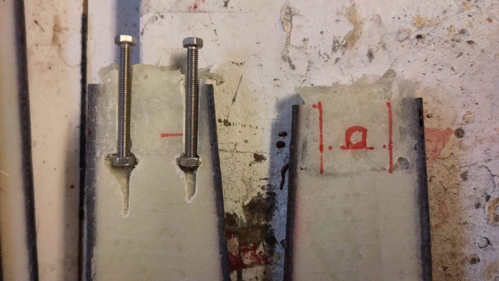
The day after I continued shaping the halves so that they would have to correct shape after glueing them together and also would fit together as pairs. For the end caps, to hold the shroud in place, I cut out and included an m5 stainless nut when glueing the two halves together. I liberally applied grease to the bolts, but not the nuts (finicky), and they came out without a problem the day after.
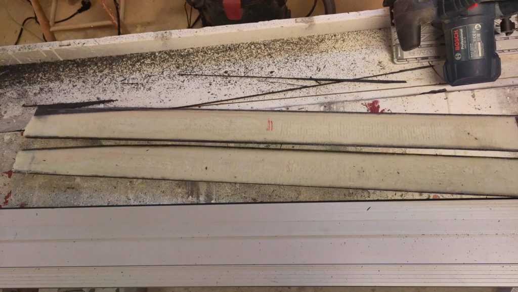
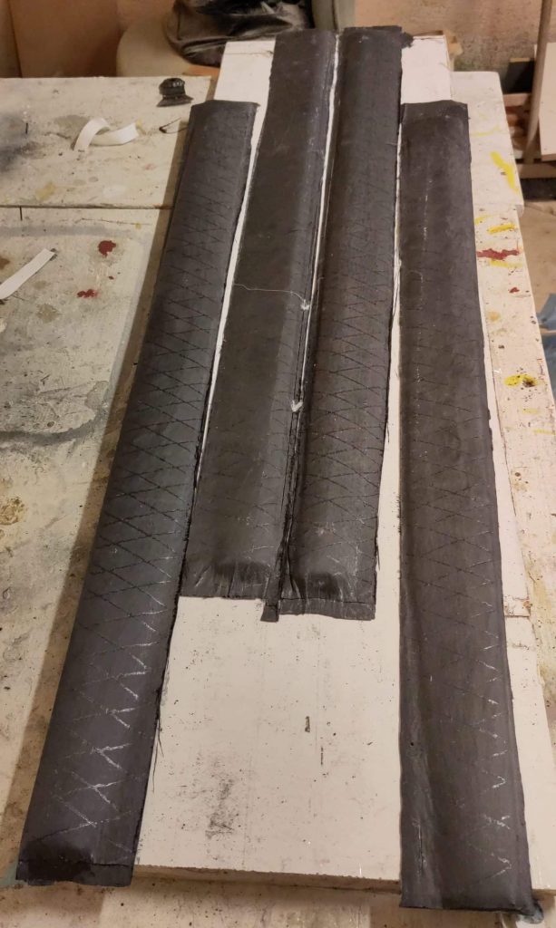
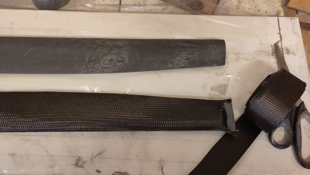
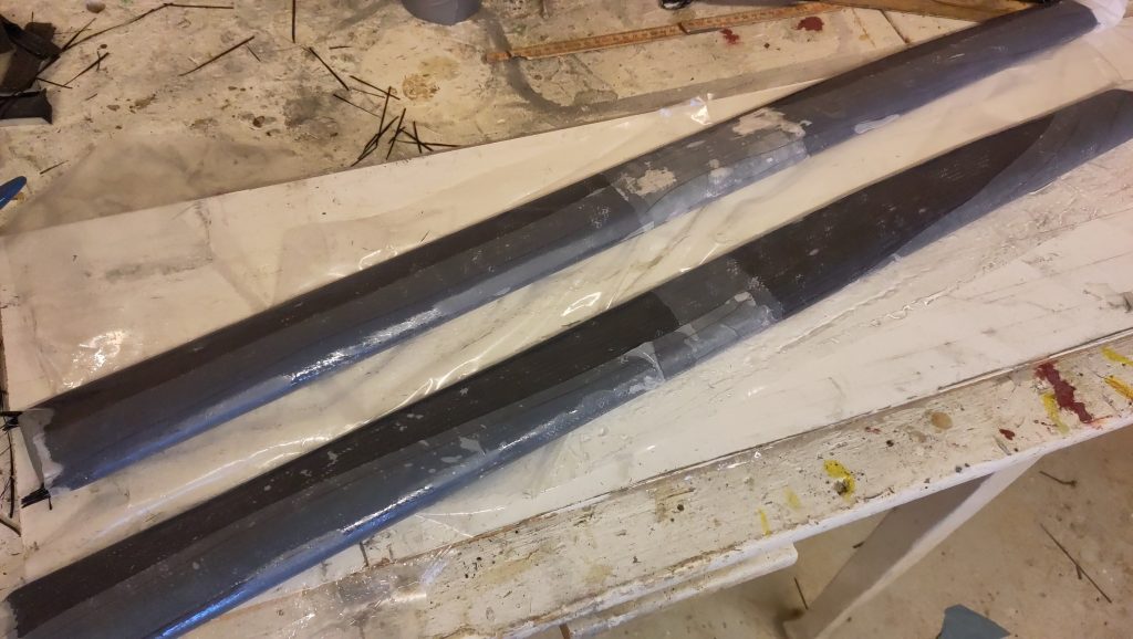
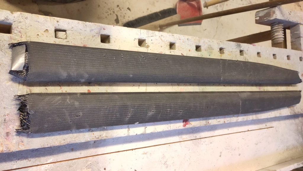
I now had two sticks. Out came the orbital sander and I knocked down some high-spots and made sure to roughen up as much as I could, before preparing the next step. I don’t trust the epoxy to hold the spreader halves together by it self, and so far there were no real torsional strength. Therefore I had previously bought carbon fibre biaxial tube which I thread the spreaders through. Since applying epoxy to the pieces before the tube would make this process even harder I elected to instead thoroughly soak it in epoxy to have some confidence in proper wetting out of the laminate. I wrapped it in peelply for easier cleanup.
Even with all of this, when unpacking I found some smaller dry spots, but I think these can be saved with a slight application of more epoxy in the next step of lamination. Left to do is cutting the spreaders to final shape, making attachment holes, some end points and mid reinforcement, before cladding the whole thing with flax fibre laminate.

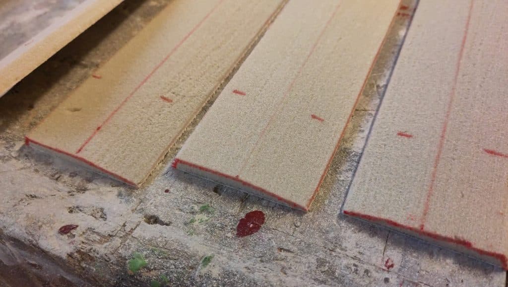
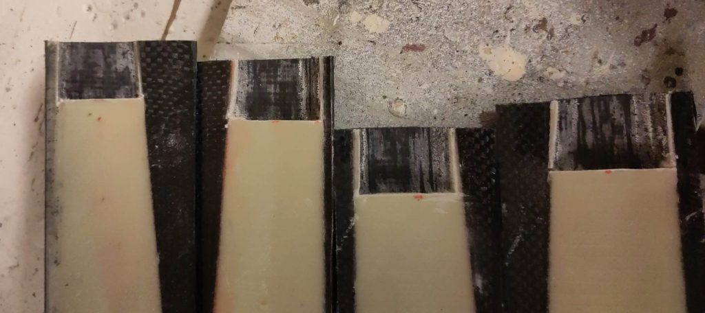
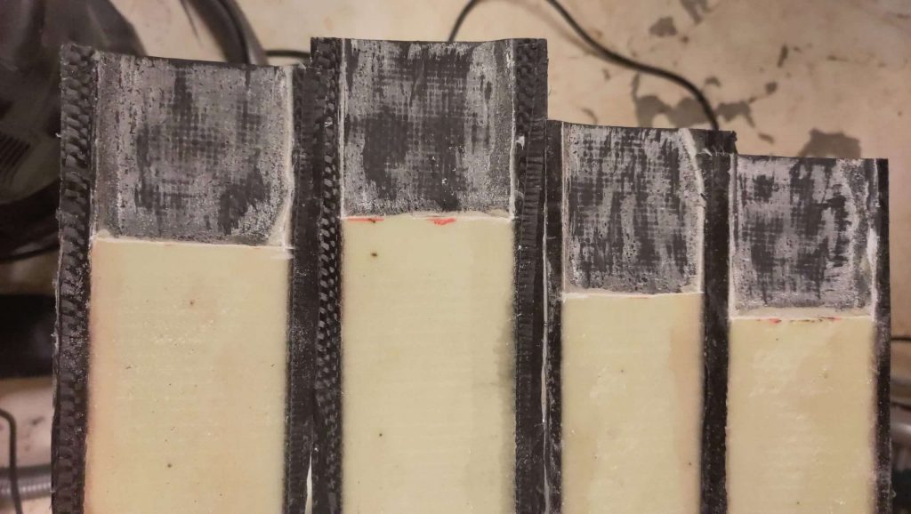
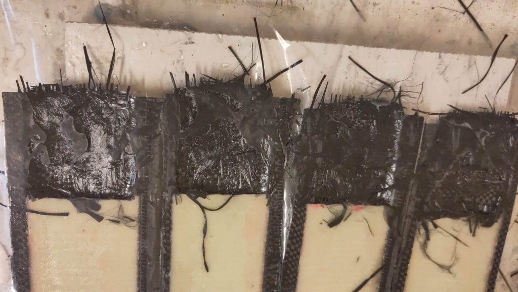
I choose to do the spreaders in two halves because I could not figure out a good way to properly strengthen the inside otherwise, while keeping the shape. The next weeked I started by removing the foam in the ends for filling out with solid laminate instead.
For the carbon fibre I started with some 5-8 layers of organised mat before filling it out with chopped carbon fibres. In the shroud end of the part, which is only going to experience pressure, I went with chopped glass fibres already from the start.
For the initiated
I mean really, skip this section.