Futureproofing the electron highways
When buying the Aquabelle the previous owner had installed a rudimentary 12-volt electrical system. Since this was in the middle of the interior rebuild it was not quite redone and it was hard to understand for an outsider how it worked. Part of the objective of this page is to make sure I or the next owner will not end up in that situation again. First and foremost I wanted to create a bookshelf and seat where the navigational table and switches were located, which meant that the breaker panel had to be relocated. I also wanted to incorporate a better support for solar panel charging, fridge and other stuff I do not want to be turned of by the main breaker. A panel in the companionway for things like deck lights, steaming lights, autopilot, etc, was also something I wanted to achieve. And lastly the existing cable dimensions from the house bank was only 16mm2 which meant large voltage drops over the total 8 meters from the house bank to the breaker panel. Voltage drops in a 12 volt system is quite bad, especially when it comes to things like charging with smaller solar panels and running the fridge. Good energy economy requires a minimal voltage drop. To calculate the required cable dimensions throughout, I frequently used online calculators as well as the fourth edition of Nigel Calder’s Mechanical and Electrical Manual, a bible when it comes to boat systems in general. One big goal was to future proof the backbone of the system because it seams in our world that we bring more and more electricity onboard, future ideas for example hold a kitchen fan.
Layout and Plans
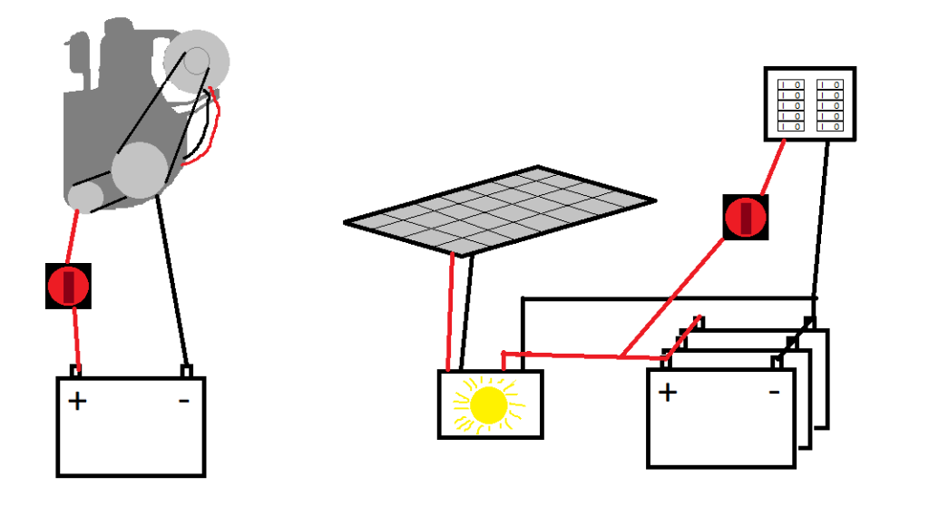
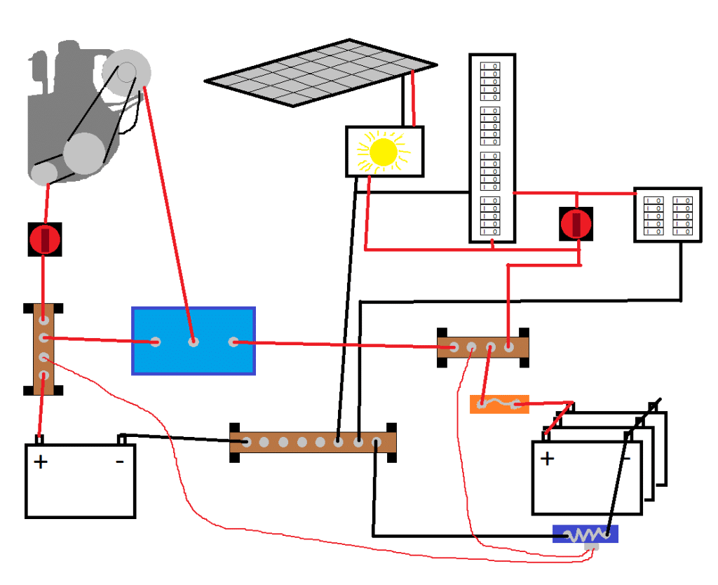
The previous system was a system with 3 AGM 75Ah batteries located under the aft berth which I will keep for as long as they will last. From them it was routed via 16mm2 and a main breaker to the breaker panels with automatic fuses and then to the rest of the boat. The solar panel regulators where connected with their own 8 or 10 mm2 cables directly to the batteries, or maybe via some kind of bus bar but I don’t quite remember. The engine starter battery was connected to the engine in a circuit of it’s own with the alternator and starter motor. This meant that running the engine wouldn’t charge the house bank. I now wanted to add a beefed up unbreaked connection to the house bank, a separate small breaker panel in the companionway, and to be able to charge the house bank with the alternator when the engine was running. I also wanted to improve the installation with a main fuse, properly dimensioned, and some kind of BMS to keep track of the batteries charge level. To accomplish this I also had to install some some busbars to be able to connect everything.
New gadgets
As you can see on the pictures the end result is a bit more complicated even though I have left out all the consumers for simplicity’s sake. The simple BMS consists of a victron BMS-712 shunt (blue with gray squiggly line) with a display in the nav-area and the possibility for bluetooth connection with an app. A shunt is a small but very well known resistance over which the current voltage drop can be measured. According to Ohm’s law then the current can be calculated. Accumulated current can then be translated into battery state of charge if the battery capacity is known. This model will also measure the battery voltage as well as a secondary bank’s voltage. This I have hooked up to the starter battery to get a better view of what is going on.
Since the house bank did not have a main fuse I decided to add one to protect against fires in the cables (orange rectangle). I went for a simple blade fuse of about 60 to 80 Amperes which should be way overkill for my consumers as of now, but might one day be the absolute peak current drawn from the batteries. Imagine all USB-ports charging, all lamps lit, kitchen fan, steaming and deck lights lit, vacuum cleaner connected to the 12-volt outlet, VHF-radio broadcasting, fridge running, etc. Highly unlikely, but should still pass under the 60 Amp fuse.
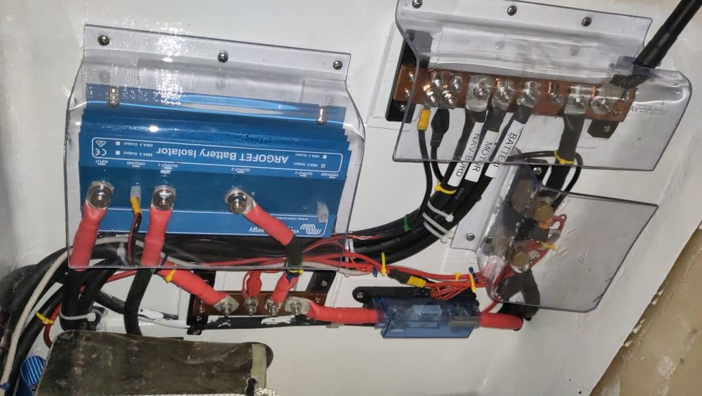
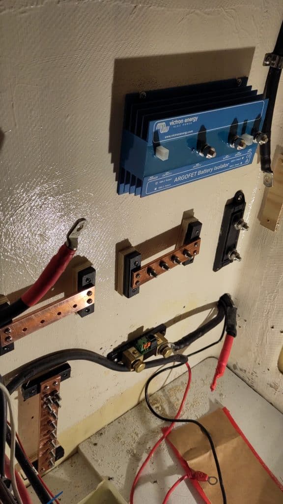
To distribute the charge an Victron ARGOFET 100-2 (big light blue rectangle) was installed. It enables charging of two separate battery banks without connecting them via MOSFET magic. It took a while and some help from some internet people to figure out how to correctly connect it to my particular alternator. It turns out that just disconnecting the positive cable from the alternator and connecting it to the input of the ARGOFET seems to work. From the ARGOFET then the positive is split to respective bank.
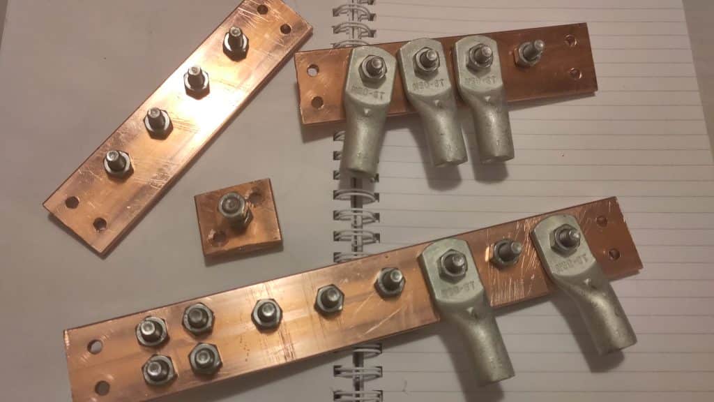
Then to be able to connect everything together I had to add some busbars (brown things with black feet). Strictly I might have gotten away with not having the one connected to the starter battery but the installation is pretty neat with one compared to not having one. These I decided to do myself since buying a piece of copper flat stock looked a lot cheaper than buying finished products. The flat stock is 5 mm thick and 30 mm wide and is mounted on some PP-cutting board plastic for electrical insulation and then the plastic is screwed to the interior.
A lesson in electrical cable dimensioning
To know what size of cables to use in the installation there are two main factors: safety and performance. The safety factor depends on the tolerable current in certain temperatures and encapsulation. The performance can simply be translated to voltage drop in the cable which the utility that is being used does not get access to, in simpler words: energy loss. To make things a lot simpler I decided from the beginning to try and stay with the same cable size for the core system if it did not become unnecessarily expensive.
If only the safety factor is to be considered we can again consult the planned max peak current usage of all the consumers in the system. In the table I have guesstimated current and future consumers to really future proof the design. It turned out that a total of about 85 Amperes needs to be able to be handled safely in the main cables to the battery. According to the Mechanical and Electrical Manual Fourth edition by Nigel Calder, from table 4-5B allowable amperage of conductors that are not bundled, sheated, or in a conduit, the minimum cable sizing outside engine compartments is then 16 mm2 (6 AWG) for a conductor insulator rating of 80°C, which is the cable type I had scouted. Conclusion then is that the minimum cable cross section area should be 16 mm2 to safely carry the amperes in the system. Funnily this was the cable size I tore out when removing the old stuff.
| Consumer | Ampers | Consumer | Ampers |
|---|---|---|---|
| USB outlets | 2.1 | Bilge pumps | 10 |
| 12 plug outlet | 10 | VHF | 6 |
| FM-radio | 10 | Instruments | 0.120 |
| Kitchen Fan | 3 | Autopilot | 2 |
| Lamps | 2 | DCDC for LED | 9 |
| Water pumps | 5.8 | Fridge | 3.5 |
| Heater | 2 | Deck lights | 3 |
| AIS | 1 | Runnings lights | 2 |
| Chart plotter | 4 | 12 plug outlet cockpit | 10 |
| Total: | 85.6 A |
Now on to the cable performance. The problem in 12 volt systems that the voltage is low so the current has to be high to get power. Power is current times voltage (P = U*I). This puts a lot of strain on the conductors with voltage drops as a results, which then require more current to compensate, which means more power consumption from the batteries. The problem with voltage drops is especially a problem when it comes to solar panels, especially in relative high latitudes as Sweden. No we have to consult tables 4-6A and 4-6B.
Ignoring the cables concerned with the engine, from the breaker panel and working with a bit of oversizing, I calculated the voltage drops in the cables. The tables in the book specifies the entire run of the cable both positive and negative so I guesstimated a bit and just assumed a doubling of the lengths measured would be a good representation. For a 85.6 amperes current to not have a voltage drop of more than 3% over 10 meters as in the case of the negative cable, a cable size of 50-70 mm2 would be the cable to choose. In the end this estimated current is a bit extreme and 50 mm2 should suffice. If I would accept a 10% drop a 20mm2 cable would suffice. To make it easier for my self I did the short positive to the positive busbar from the batteries the same size (50mm2) since it should be able to carry the same current.
For the positive runs of cable I wanted to try and standardise a bit and went to calculate the largest and then use that for others. 63 amps over 9 meters (to main breaker and then to the main panel) with 3% voltage drop requires a cable area of 35mm2 which is what I went with for these runs. It is a bit overkill for the part which do not have the main breaker (solar panels, fridge, heater) but since I wanted the most out of what I can get from the solar panels this is what I went with there as well.
| Placement | Peak current (A) | Length (m) | Dimension (mm2) |
|---|---|---|---|
| Main breaker - Main panel | 46 | 3 | 35 |
| Main breaker - Companionway panel | 17 | 1.5 | 35 |
| Positive busbar - Main breaker | 63 | 1.5 | 35 |
| Positive busbar - consumers | 22.5 | 3.5 | 35 |
| Batteries - Positive busbar | 85.6 | 1 | 50 |
| Batteries negative | 85.6 | 5 | 50 |
For the cables connected to the engine I just went with what was there before and installed 35mm2 cables, which should be fine according to the aforementioned tables. The starter motor draws about 100 amperes during short bursts and the generator is on about 35 amperes. 80°C temperature rating in the engine space with 35mm2 would safely let 136 amperes through which is quite a lot more than is needed. Once again the requirement for not to much voltage drop is the one that limits the cable size.
A confession
I have not been totally truthful to you. This build was not as straight forward as it might seem from the design description. I did not plan it this well from the beginning. I mean, the cable dimensioning and and basic layout was planned, but the design evolved over two seasons with a summer of testing in between. From the beginning no ARGOFET was incorporated and thus no extra busbars were created. However, during the first summer of testing it became obvious that charging the batteries with the engine was a must for the current amount of gadgets and solar power available. So the second winter in this build I had to carefully plan were to cut the expensive cables, buy some new ones, figure out how to connect the ARGOFET, build busbars, and since there now were many naked nuts and bolts, protect everything with some Polycarbonate plastic. Therefore the build did not progress in the way I will describe but was rather many iterations back and forth.
Main breaker panel
This work was done in tandem with the build of the navigation station so if you have not read the page about that I highly recommend you to.
I wanted to extend the number of breakers so that each individual gadget could be turned on or off without affecting other things, and as usual I wanted to keep costs down, all while trying to fit the panel into the navigation station requirements. I therefore decided to order separate switches and ATO blade fuse boxes to build the main breaker panel with. To keep the theme I did the same for the panel that was created in the companionway.
I first measured out everything to sanity check and get a feel for it before I committed the Dremel the the newly build panel. I mounted everything on plywood bits with two objectives in mid: to get a better hold for the screws since it is just a thin layer of fibreglass and then styrofoam, and to be able to cable manage behind all the apparatuses. I also decided to keep the whole panel wiring as a unit making all the connections connect at one end and to the negative busbar in the bottom.
As you might see the original plan did not quite hold up. The bottom five breakers were later
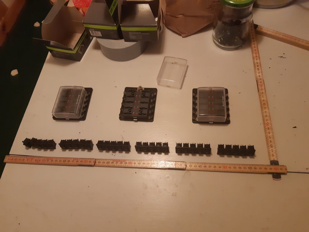
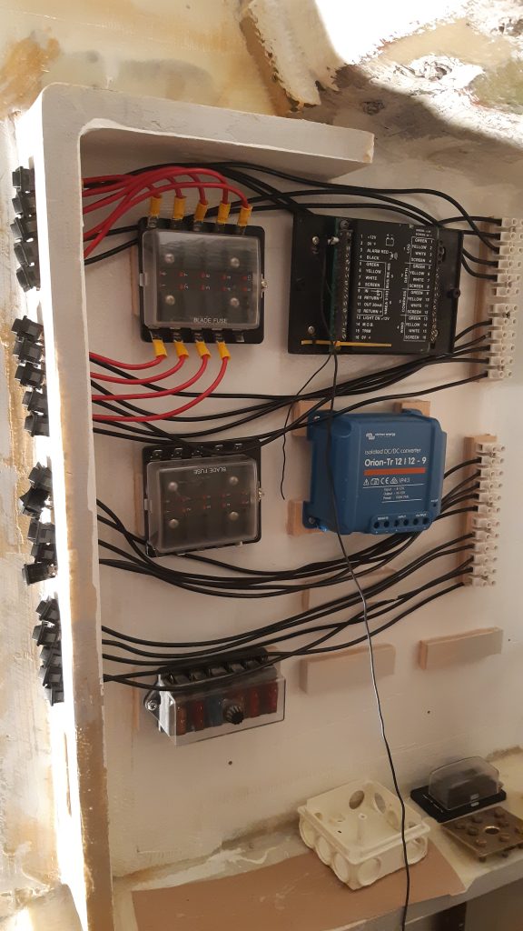
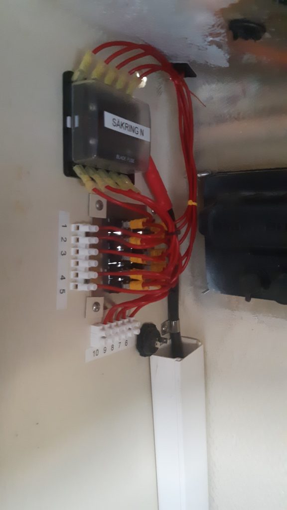
replaced with 12-volt and USB outlets and the third fuse box was replaced to one without common input so that these fuses could be entirely separate from each other and utilised for fridge and such things. There was also a smaller fuse box added for the solar panel regulator fuses. I never plan on having more than 4 regulators so that should be well future-proofed.
A DCDC converter was also added to drive some ventilation fans and LED-lighting so that no disturbance is spread in the electrical system. Even though not hooked up yet, it should also be possible from the BMS-712 turn this DCDC off automatically if voltage drops to low.
Companionway breaker panel
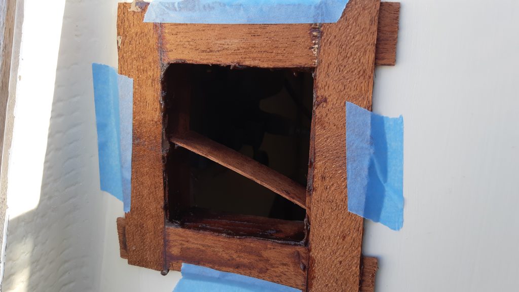
Well, to be honest, there are more picture about this than information. I consulted with some increasingly external parties (friends and family) many times before I dared to put a hole in the companionway. The problem is that almost directly above this there is a winch mounted. That will exert a big amount of force with the bulwarks in the companionway taking upp a part of that force. In the end I cut the whole and it hasn’t broken yet.
To fill the ugly hole I made some trim which I glued in place. This was a slight mistake since it took forever and some destruction to get it out again for finishing the form and varnishing.
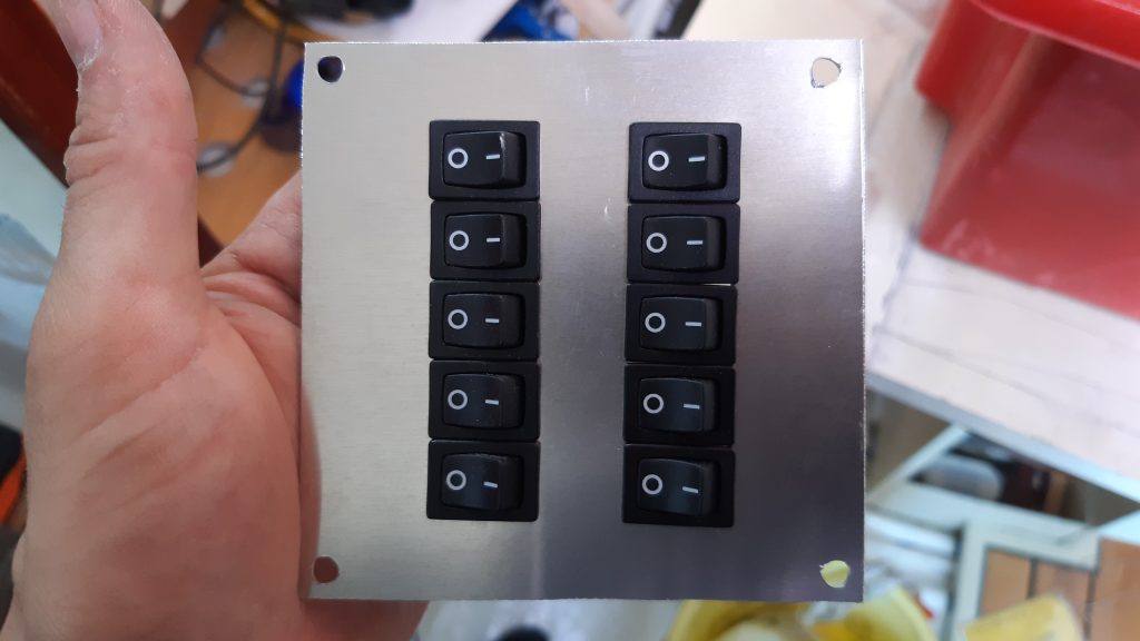
I mounted the breakers on a piece of aluminium that I screwed and glued from the backside with some TEC-7. On the back I also mounted a fuse box and made the wiring to connection places in which it is relatively easy to connect stuff. I later also added a 12-volt outlet for search-light, anchor light, VHF charging etc.

Busbars
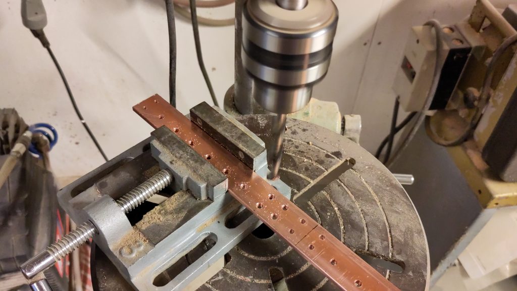
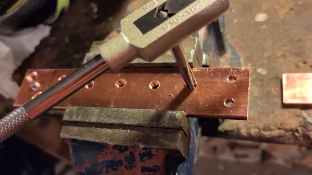
Busbars are apparently quite costly compared to a plain bar of copper so I decided to make my own. The bar is 5*30mm CW008A SS 5011 Copper which should be well overkill with regards to the currents that will go through it, but the sizes were needed for my limited machining competence. I think the price was about 200 SEK in 2022 when I bought it.
Not much else to say really. Cut, drill, thread, and then mount on some plastic pieces for electrical insulation.
The behind-the-scenes
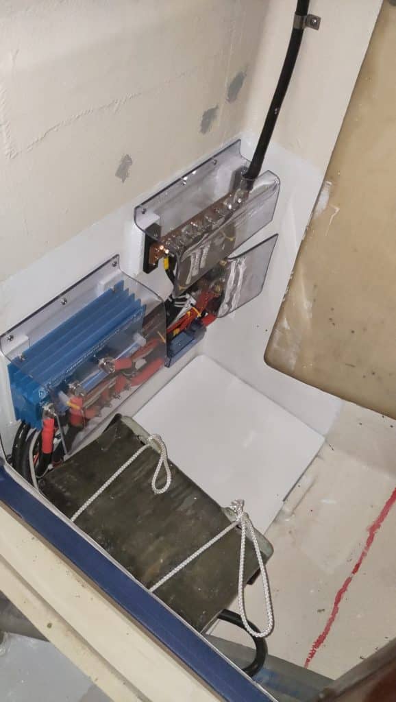
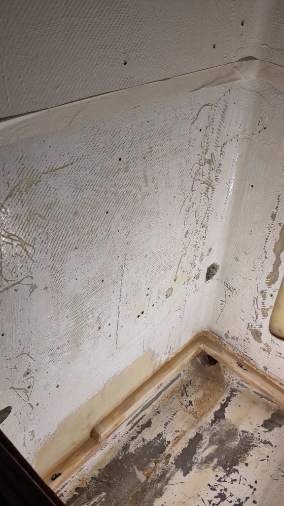
Now we get to the actual system, kind of. This is mostly placed behind the toilet in a closet. I have always had problems with this space because it is collecting water when it is raining somehow. Through fault-tracing with watercolour I have concluded that most of this water comes from the ventilation channel. This will be fixed at some later point.
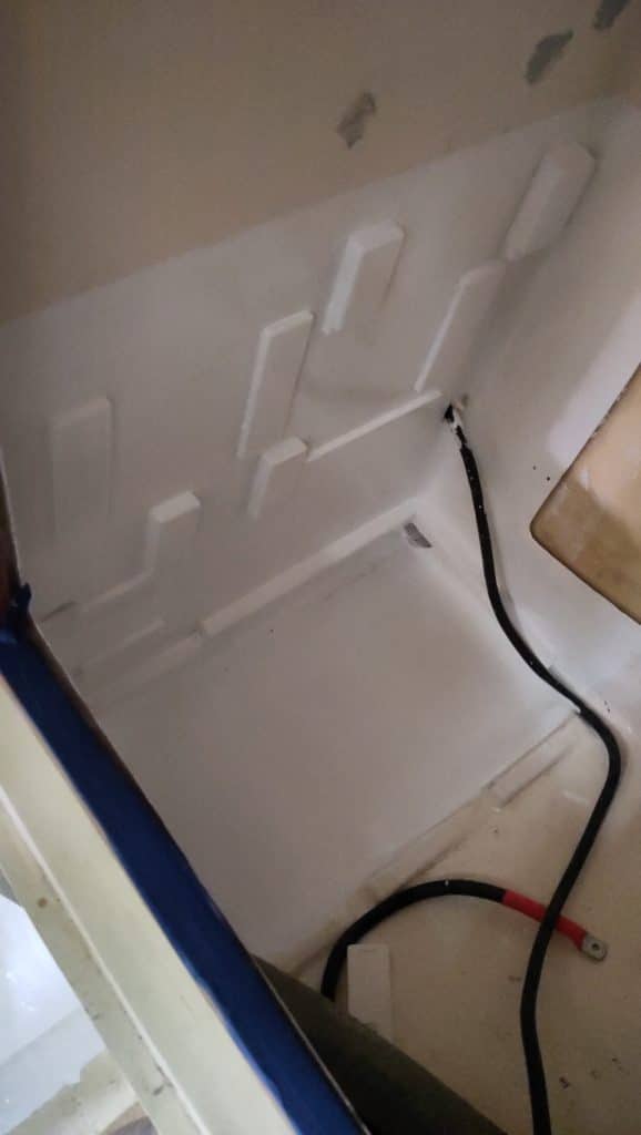
But to avoid standing water I decided to cut a hole for the water to escape out to beside the toilet. This then means that it is visible and can be mopped up. I also decided to add some floors to this space so that the bilge hose would be protected and the starter battery better supported. But out came the sander. Since I was doing some painting of the bilge at the same time I decided to make the surface under the electrics nice as well.
Similarly as the main breaker panel I decided the mount all the stuff on plywood to make them really be attached. It was also required to actually get the cable attachment points on the same plane. This was needed to make the, sometimes, very short cables from having to bend too much.
Figuring out placements and finishing
As usual when I work like this I start by drawing on paper, then mock up with cardboard in the space and then continue with the actual pieces before deciding where everything is finally going. As you can see in these pictures not even the mock up with the actual pieces were the final location. But that is how it is sometimes, iterate, iterate, iterate.
Since there now is a lot of nuts and bare metal that is in the electrical system in a space were potential metal things and sometimes maybe moisture I decided to cover everything with clear Polycarbonate plastic. It makes it a bit harder to work with the system but will hopefully avoid sparks.
