This idea started during the autumn of 2017 when I read Principles of Yacht design by Larsson, Eliasson, Orych and is pretty much a continuation of the semi-failed catamaran build. The idea was very similar but extended. It was still going to be possible to hoist it up on a car roof – hence a bare hull weight of 60 kgs or thereabouts was desired. The goal was to be able for two not so heavy adults to go out on a weekend trip on lakes, bringing all the equipment for an overnight on some island. So two adults of 80 kg + 20 kg food and equipment each = 200 kg. A hull weight of 60 plus spars, rudder and some other stuff, I figured a design displacement of 300kg was the goal.
The construction technique I figured in the beginning was going to be some form of plywood on frame construction similar to what I id on my catamaran build. During the development process this got changed to stich and glue, where precut plywood boards are stitched together with wire of zip-ties and then the joints would be covered with glass fibre.
One issue is to get hold of some cheap rigging and sail, and I figured that there must be some second hand Optimist-sails and rigs that I could buy. Only one opti-sail for two adults was not going to be nearly enough so I had to get two of them, add a foresail and maybe some top sails to them as well for light weather sailing. I also got some inspiration from youtube regarding this.
Two opti riggs after each other along with a foresail would mean a very long boat. I started work on some pilot design to find out if 60 kgs on the hull would be feasible.
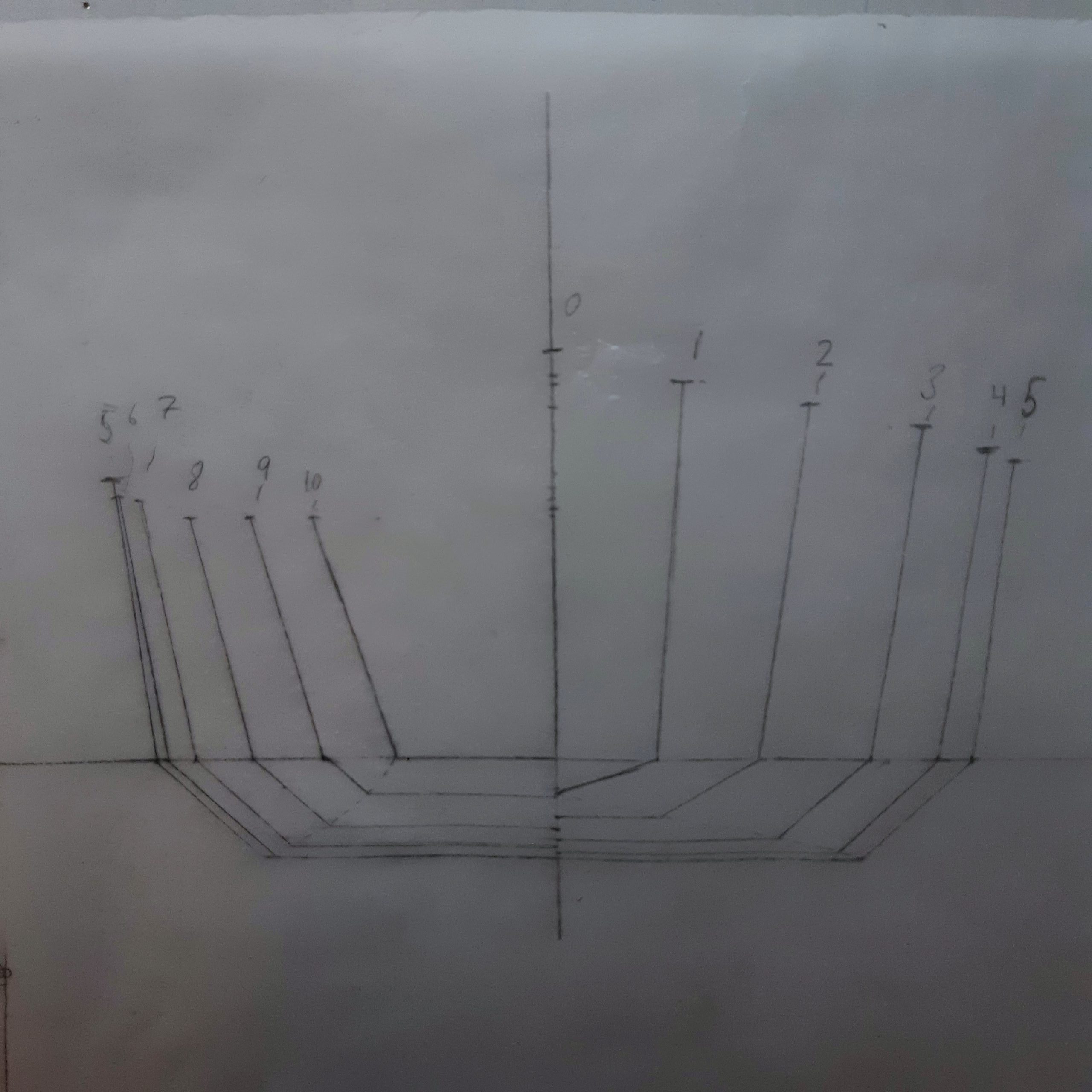
Mk1
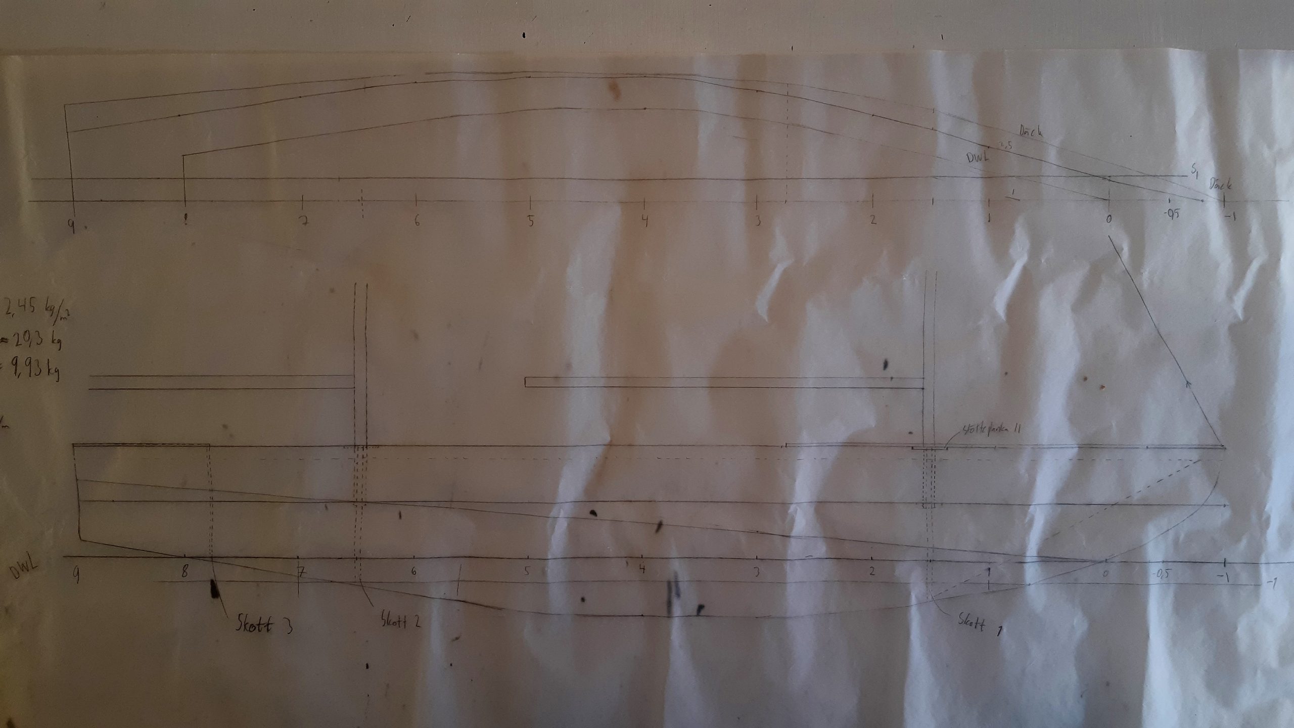
I do apologise for the poor quality of the photos of my drawings. Improvements to them will have to be done some other time.
This first iteration have a very deep hull, due to me trying to go for a more classical shape. The narrow waterline also probably means the the boat will not be very stable. Some numbers:
| Displacement | 305L |
| LWL | 4m |
| LOA | 5m |
| Surface_hull | 8,28 m2 |
| Weight | 100kg |
Well, it needed to get more stable lighter and better looking. It looked promising though. On to the next iteration.
Mk2
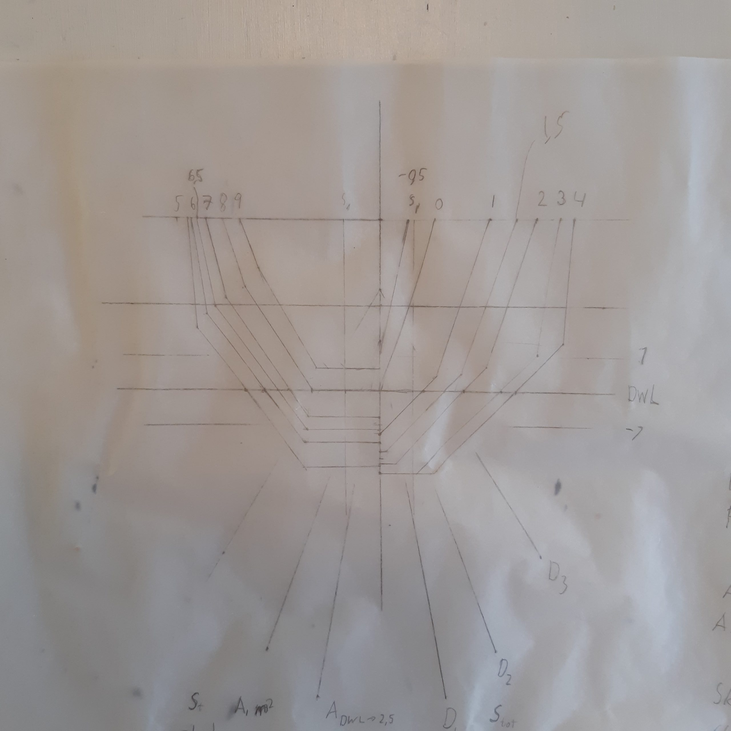
For the mk2 version I wanted to achieve a more stable hull, smaller area to get it lighter and I also lowered my design displacement to 280 kg, allowing it to float deeper in the water if design carrying loads were exceeded. I did hope that a lower surface area and more attention to detail would lower the weight of the hull so that the lighter displacement would not be an issue.
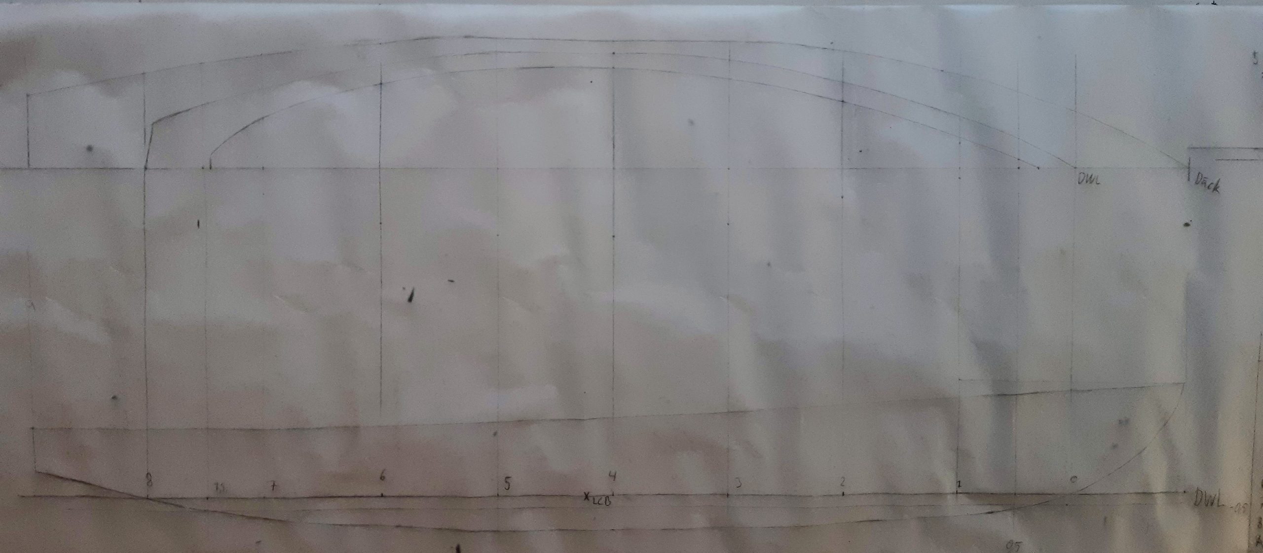
My main change was to make the hull waterline breadth wider and the draft of the hull more shallower so as to increase the stability. To combat the weight problems I lowered the freeboards, especially aft. The bow I kept high since it is a small open boat, you don’t want to get waves over the bow. In this I was still attached to the idea of overhangs, but now I also started to calculate the center of effort of the sails and found out the it is very much aft. One of the main concerns I had at the time seems to be the weight. I have written suggestions on lightening actions on the plans: removing aft overhang -1,5 kg, going up from 4mm plywood to 6mm plywood (+9kg) but being able to remove an inner fram (-15kg). Some numbers before we continue over to the mk3:
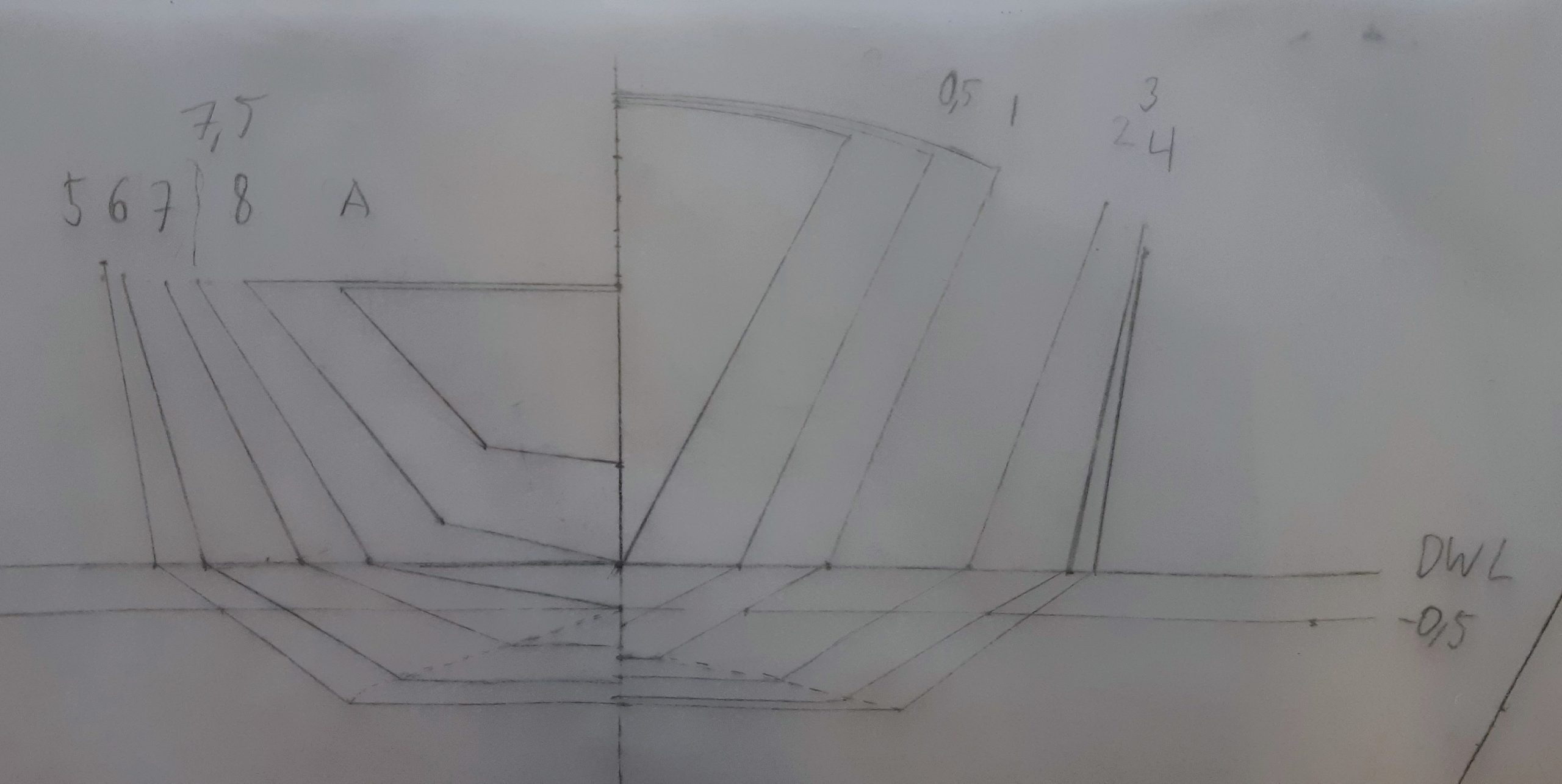
| Displacement | 282L | ||
| LWL | 4m | LAO | 5m |
| BWL | 1 | BAO | 1,1 |
| Surface_hull | 6,9 | ||
| Surface_wet | 3,97 | Surface_dry | 2,93 |
| Total weight | 83kg | Hull weight | 63kg |
| Sail area (SA) | 7,3 | ||
| SA/D one person | 17 | SA/D one person | 22,9 |
Mk3
For the mk3 design I realised that the center of effort of the sails had to move forward to be able to have the centreboard at a more reasonable location and have a more directionally stable boat. So the sails had to move forward and the boats aft end had to get longer in the water. I also came to the conclusion that if speed was wanted a longer waterline is desired. This meant two things: a bowsprit and a waterline length that was the same as the length over all. With this in mind I looked at the style of older working boats, especially the Bristol channel cutters. Here’s what I came up with:
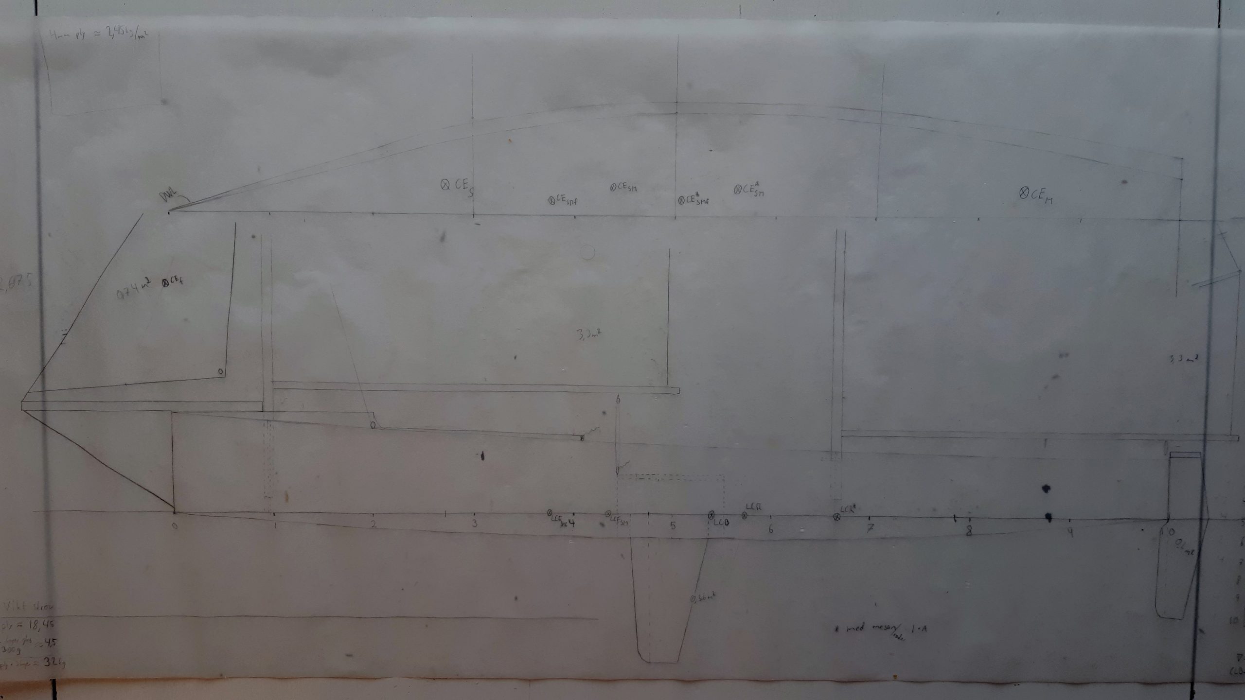
As you can see this was also the point in time in which I started having a proper look at centreboard and rudder design. I also at some point started on a model of it to get a better idea of what it would look like. I tried putting some cardboard hull planking on it but it didn’t go so well, so I quit. The design number except the length didn’t differ that much from the mk2 so I wont waste space on them.
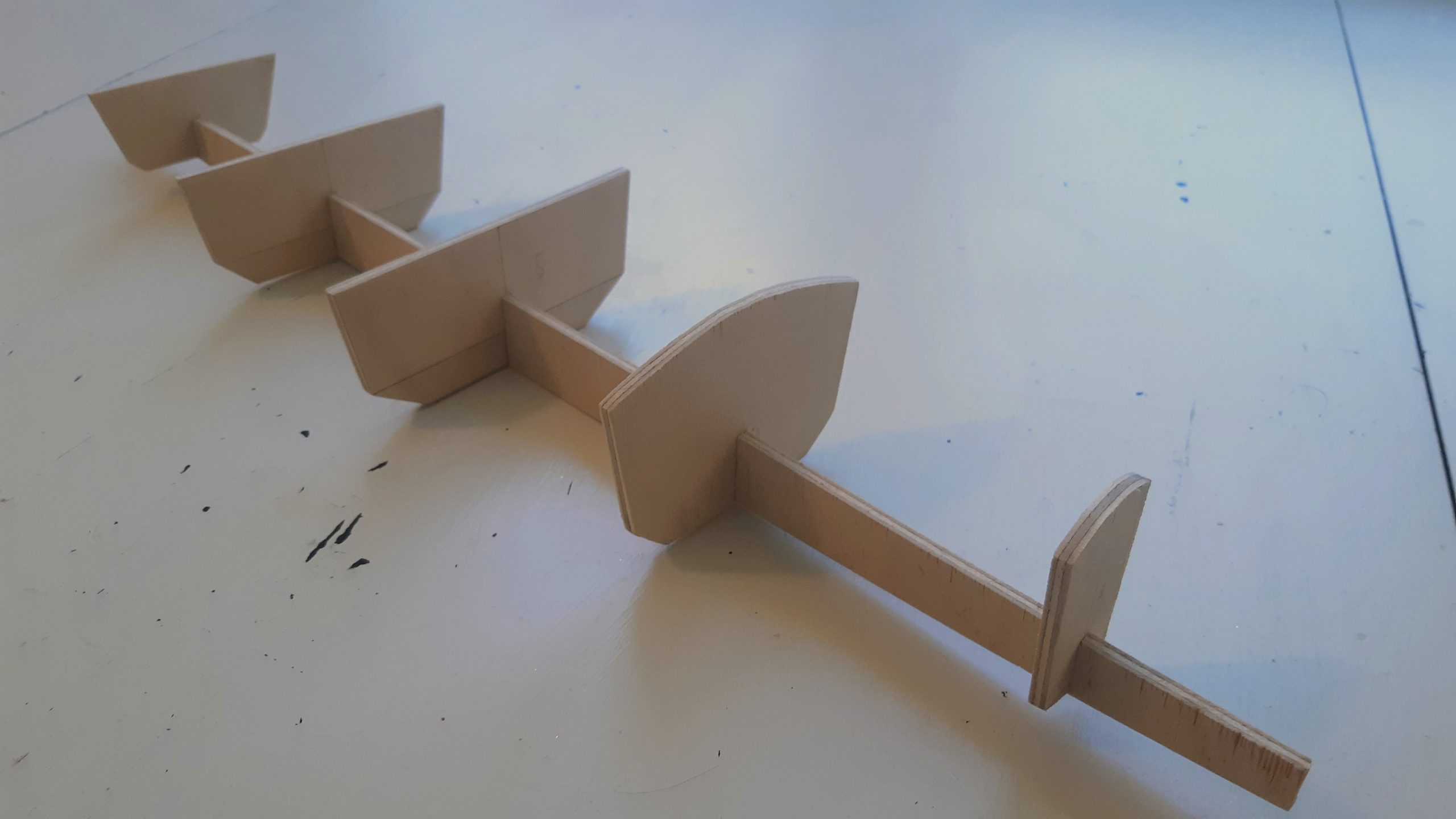
Computer iterations
Along came 2020 and Covid-19. During the spring the company at which I as employed temporarily cut down on the working hours for its employees, with almost no reduced pay due to the Swedish government compensation. I found myself having to spare weekdays a week with nothing to do so I took up this project again. With the mk3 under my belt I felt it was only so much I could do on paper so I decided it was time to move my development to CAD where modifications to the designed hull goes quicker and it spews out numbers automatically.
Delfts University in the Netherlands have made their early modelling software available (DELFTShip free) and it has continued being somewhat developed independently as FREE!Ship. This is the only software to my knowledge that does boat hull CAD with appropriate degrees of freedom, and that is also free to use. FREE!Ship can be found on SourceForge and DELFTShip free can be found on the webpage. The software lets you from a sample hull that you choose define the initial dimensions, then modify the hull shape to your liking. Numbers such as metacentric height (measurement related to stability of the hull), designed displacement, displacements at different depths, center of mass and center of floatation, center of lateral resistance etc. It also compares the principal characteristics of the hull being designed with statistical data of some known hull series and you can get some approximation of the water resistance.
To have a little bit better understanding of the resistance of the hull in the water I used another software which is called Michlet and is developed by the user daiquiri over on www.boatdesign.net and can be found if you look around over there in some old threads, e.g. this one. It is build using the thin ship theory of resistance. Since the hull I was designing was 5 times longer than it was wide it was a bit on the fatter end for this to really be applicable. I was mostly interested in qualitative comparisons between hull shapes that where very similar so I figured it would be ok, especially since it is a private project. The program is mostly applicable for catamarans of trimarans since they generally have much thinner hulls, so the program has support for analysing wave pattern interference between the hulls as well, which is quite cool. If you now a little bit about general waves you of of interference. Now the waves made by the boat are in related to how much the resistance of the hull is. All the energy used to push the boat has to go somewhere and it goes into the waves created. If you design a catamaran where the design is so that the wave pattern created by the hulls cancel out through interference the resistance is in theory much reduced.
Most importantly FREE!Ship has the possibility do do “developed” plates. That is, if a hull is being designed with sharp corners the program can unfold the hull and put the different pieces flat on a plot. This enabled me to print plotting tables on plywood, then saw out these very weird shapes that in the end would assemble in the hull shape that I had designed. So halfway through the design process I had to switch from DELFTShip free to FREE!Ship.
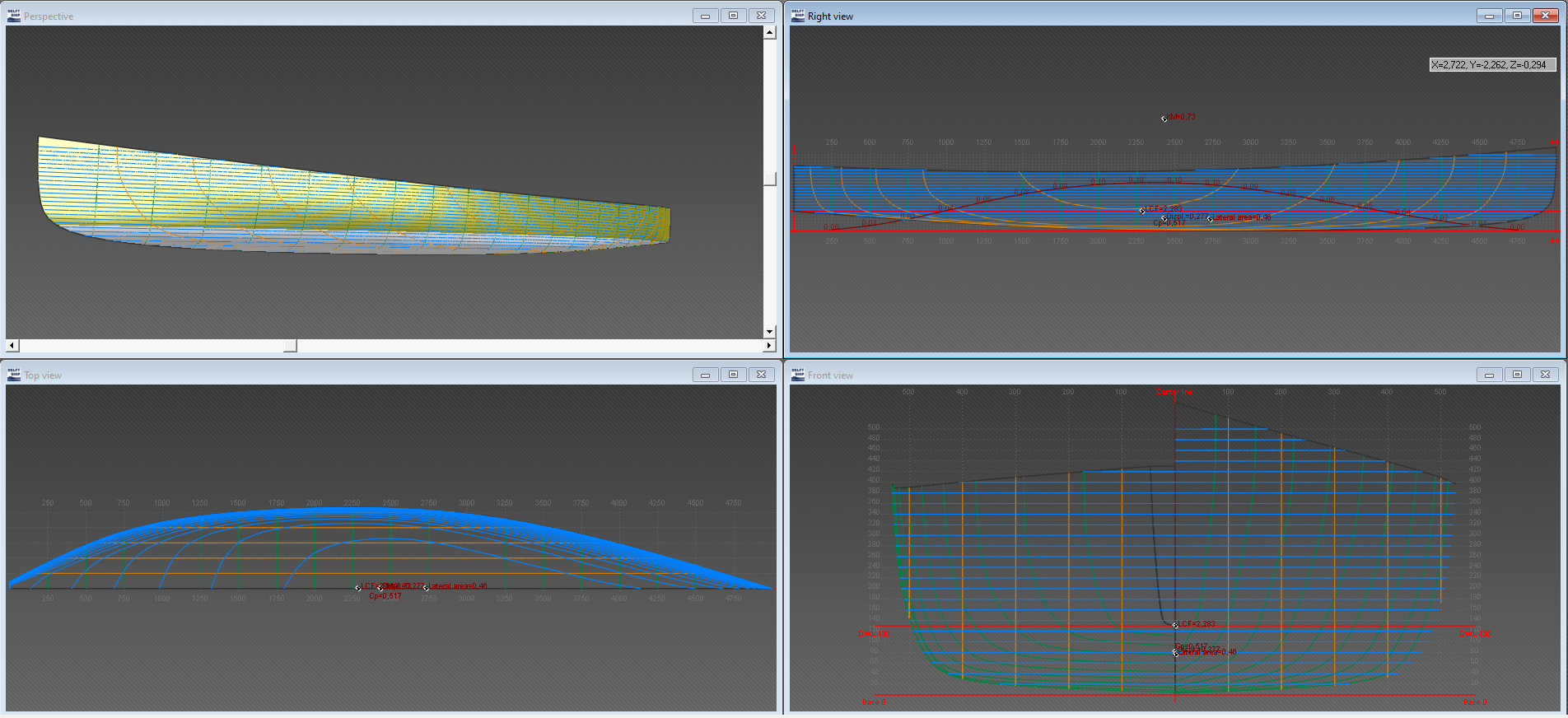
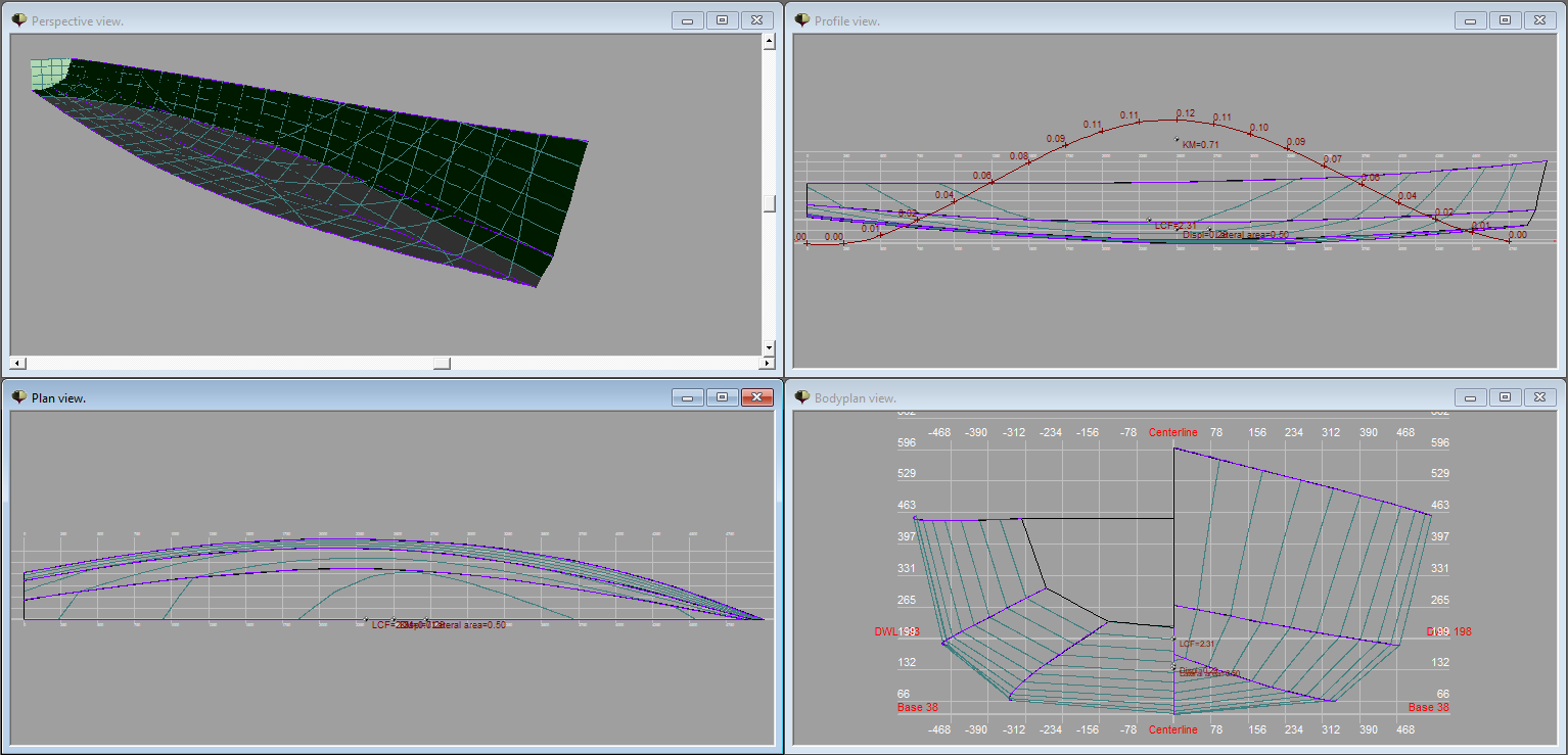
Well I did a lot of iterations at the same time I did some cost calculations. The original though was to use stich and glue with 6mm ply, epoxy and glass fibre, but since epoxy is very expensive I started to look at alternative production methods. I dabbled a bit with foam cored polyester layup since this would be very light and basically the same price as stitch and glue with epoxy for my project. I decided against this though with time constraints in mind, me and my uncle who was going to help me build only had a week and half to build it. In the end I settled for stich and glue 4mm plywood and 3 layers of 300g glass fibre matt with polyester resin on the outside to help keep the structural integrity. The main problem with polyester is that it doesn’t bond very well to, well most things. That’s why the added form stability of the glass fibre. Normally with epoxy only glass fibre on the seams between the plywood is necessary. Some even swear that the thickened epoxy use to glue the panels together is enough, if done properly. Enough text, here’s some pictures of some of the iterations in order before moving on to the final one.
According to my savefiles the Mk3 is last touched the 21st of March 2020 and the Mk17 was completed some week before we were going to start to build id in the end of July, not working even part time with the design though, more like a day a week maximum. I also made lists of materials needed (25kg of polyester for example) where to buy them, time schedule, a small attempt at simulating the hull with OpenFoam which I gave up, etc.
What has really changed from the mk3 to the mk17 you might wonder. For the visuals I can point out that the bow has gotten a more of a sloping style to it so that will probably help with handling waves and lowering weight, it has also gotten a little bit blunt for crash resistance, imagine children docking the boat by sail. The hard chines of the hull has moved from one of the following the waterline, to instead one being completely out of the water and the other completely in the water. This is what makes hard chined boats ugly in my opinion, that’s why I drew the mk3 as I did. The stern has changed from being 4 sided to 6 sided. As you might have noted the Mk3 I did actually model on the computer as well. Let’s compare the numbers to understand more of the subtle changes that are not easily spotted on images.
| MK17 | Mk3 on computer | Mk17 | Mk3 on computer | ||
|---|---|---|---|---|---|
| Displacement | 278 L | 272 | KMt | 0,816 m | 0,692 m |
| LWL | 4,812 m | 5 | LOA | 5,012 m | 5 |
| BWL | 1,014 m | 0,980 m | BOA | 1,171 m | 1,093 |
| Surface_hull | 7,093 m2 | 7,630 m2 | Hull_draft | 0,14 m | 0,12 |
| Surface_wet | 3,665 m2 | 3,693 m2 | Surface_dry | 3,428 m2 | 3,937 m2 |
| LCB | 2,337 m <-> -3,39 % | 2,296 <-> -4,07 % | Waterplane_area | 3,393 m2 | 3,422 m2 |
| CP | 0.5594 | 0,5132 | Entrance angle | 17,931 | 14,11 |
The changes other than purely visual can be summarised in two points.
- The hull has been wider over all as well as other small changes to the shape, to increase the stability which can be seen on the transversal metacentric height (KMt). This is an importance stability metric that is valid for small angles of heal. The righting momentum RM is related to the metacentric height over center of mass GM as: RM= (m*g)*GZ = (m*g)*GM sin(phi). Guesstimation wise, assuming the center of gravity being about 2 dm off the waterline with people in it, the fundamental stability has increased with (0.816-0.2)/(0.692-0.2) = 25 %. Quite a lot in other words. This with a smaller hull surface due to the lower freebords. The boat will probably handle waves worse (maybe compensated with the shape of the bow), be able to carry more sail in the same wind but you have to be quicker to compensate for gusts so that the lee freeboard does not get submerged.
- The prismatic coefficient which is calculated with the formula Displacement/(Submerged_max_sectional_area * LWL). In words one can say that a value of 1 means that it is a cylinder, a cone has a value of 1/3. It is an important metric for predicting the performance with regards to its designed purpose. The classic idea is that a pointier boat (lower CP) is better upwind while fuller ends (higher CP) are better offwind. A value of 0,55 is what is recommended in Principles of Yacht design for a not-extreme all purpose design. As you can see the Cp has changed from 0.5132 to a value of 0.5594, a design a little bit more suited for off wind, but with the sailplan I never expected the boat to be an upwind machine anyway. This at the cost of the entrance angle though which has changed from 14 to 17 degrees. A smaller angle means less resistance in the water.


