Preparations and start
The whole build actually started with me going down south to my parents to borrow one of their cars. I then drow back home and finished the preparations. During a couple of days I did a number of small final preparations. I put together the final offset tables to be able to plot out plywood panels for the boat, materials where anxiously waited for from the mail, I picket upp the buckets with polyester and other things, and I calculated how to most optimally cut the ropes that were going to be used for the sails. Then on a Wednesday I filled the car with all of the things I was going to bring and began driving to my uncle for the build. On the way I bought some beer, which was going to be needed, and food for the construction time. I arrived some time during the evening and planned the last things. The next day I went to buy plywood, materials for the hardback and spars. I had not managed to get hold of second hand spars so we would have to make out own. More on that later. We needed some not-free spruce though which is not very easily found in the normal places. My uncle still had not vacation but met me at the shop and helped out picking through the lumber.
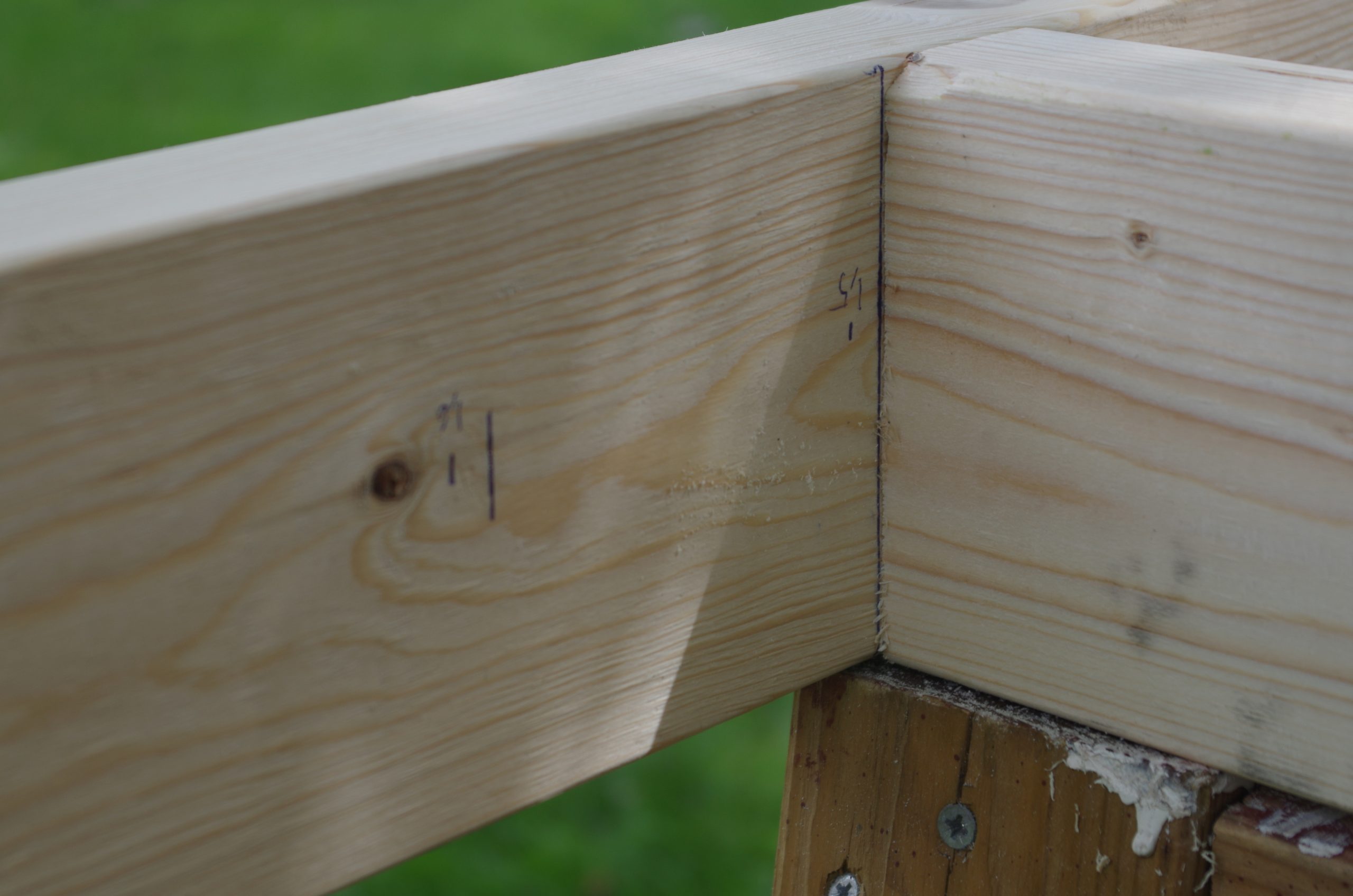
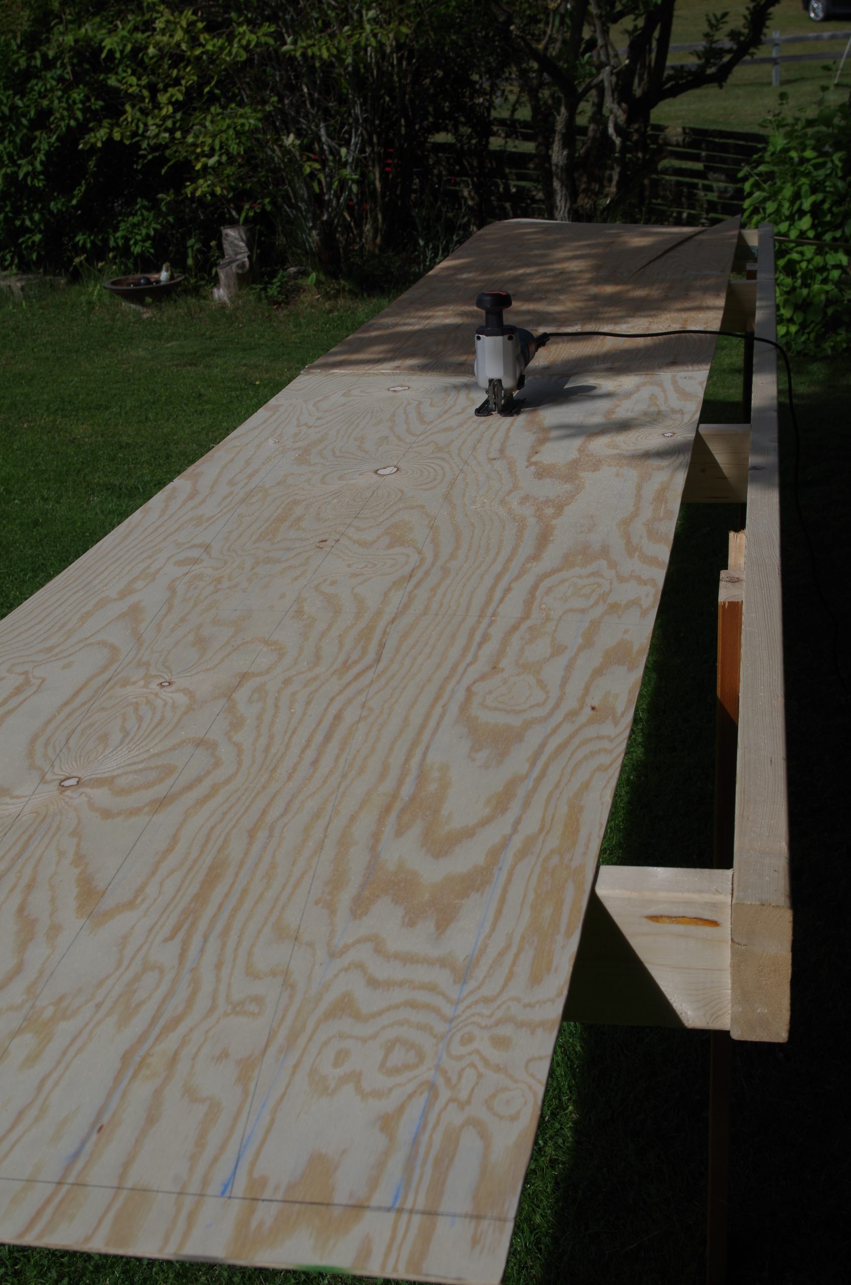
Since the boat is 5 meters but with curved sides, I needed strips of plywood that was 5 and something meters long, which forced me to try and join several plywood sheets together (In Sweden they come in size 2440 x 1220 mm). I tapered the edges on all the edges that were going to be glued with a ratio of length to thickness ratio of 12:1 with a power planer.

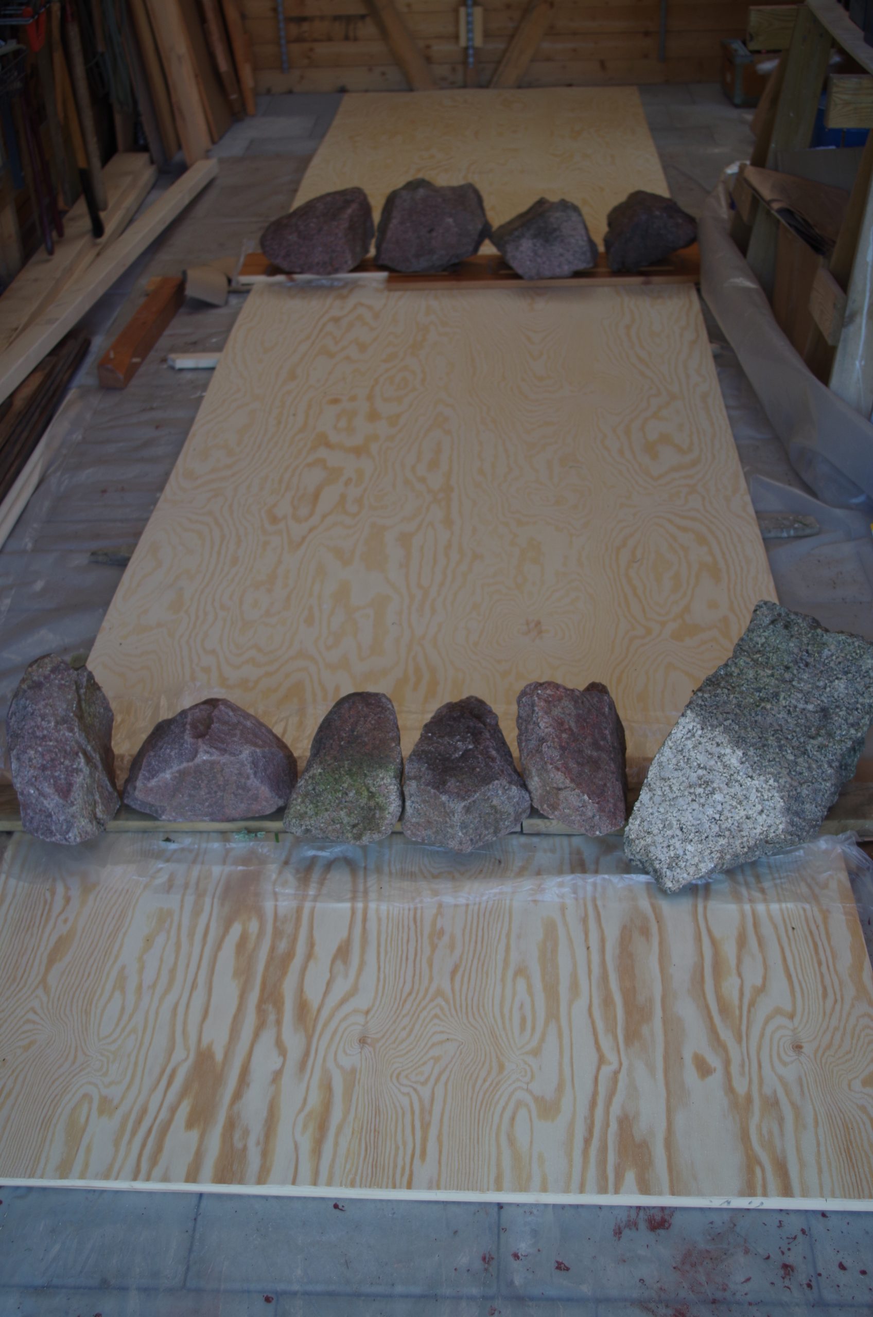
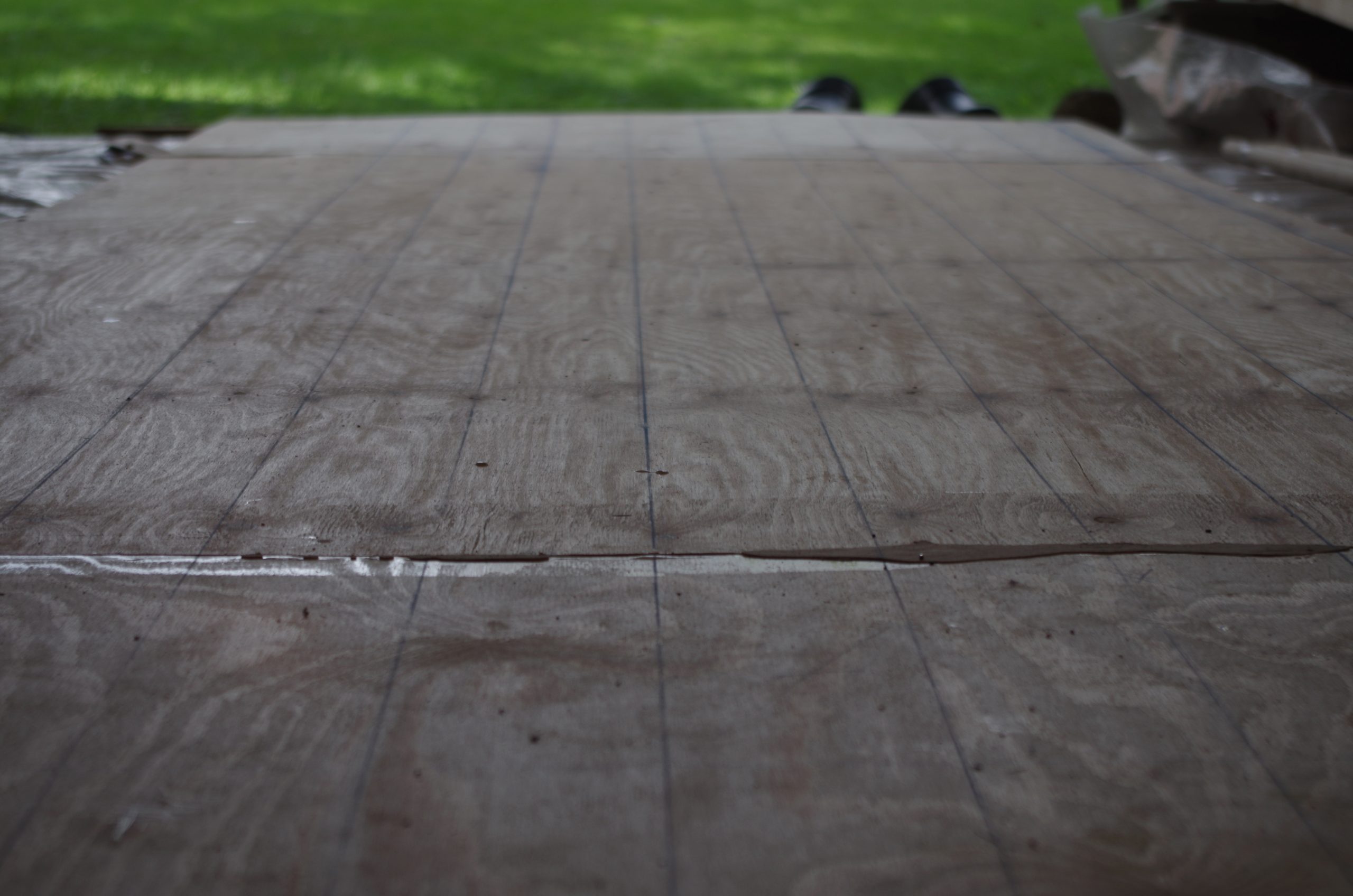
Maybe it should have been a longer joint but it kind of worked. For the glue I used polyurethane glue to make it properly water proof and to get a good bond. My parents happened to be driving passed this day on their vacation road trip so my father helped me glue everything up. I wont be keeping to which day we did what, we worked 12-16 hour days so it is quite blurry what happened when.
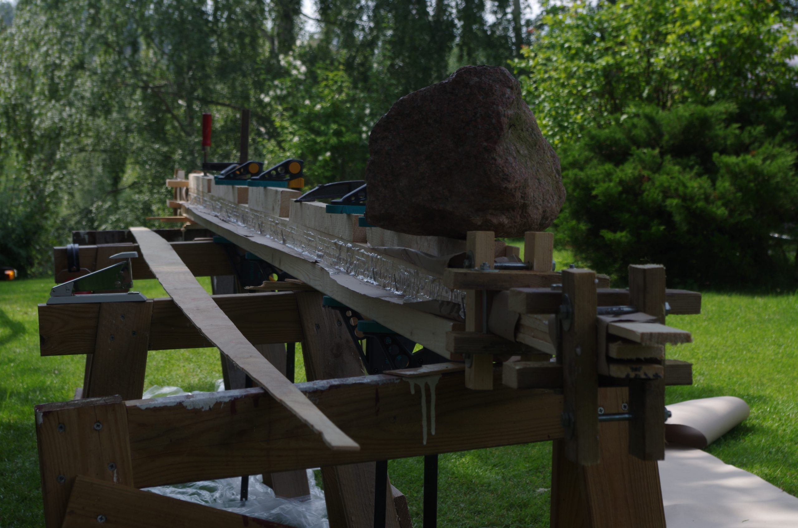
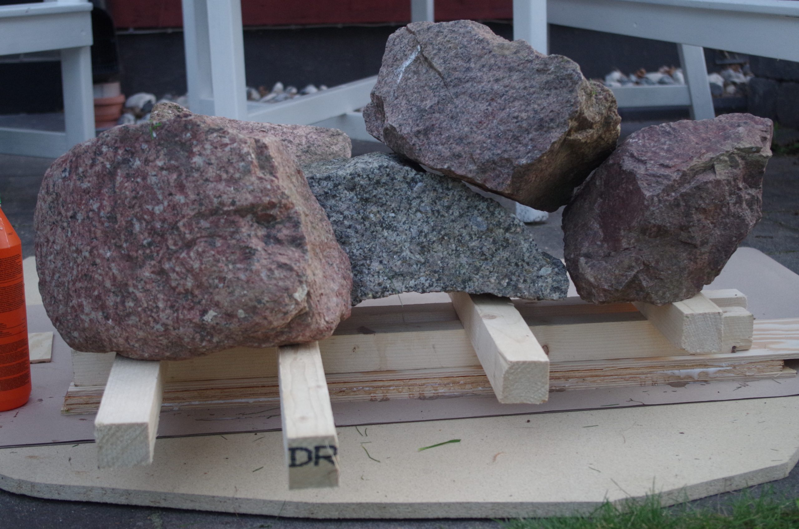
I did two very long sheets, one for each side of the hull. The layup is started with one layer plastic to protect the floor, then a plank to get a flat surface, then thick paper that is commonly used to protect the floor when painting, the the joint, then paper, another plank, paper, next joint, paper, board, and then lastly stones on top to get the pressure. I suspect one of the issues with the joint was to get enough pressure. It got glued though and managed to stay together during the building process.
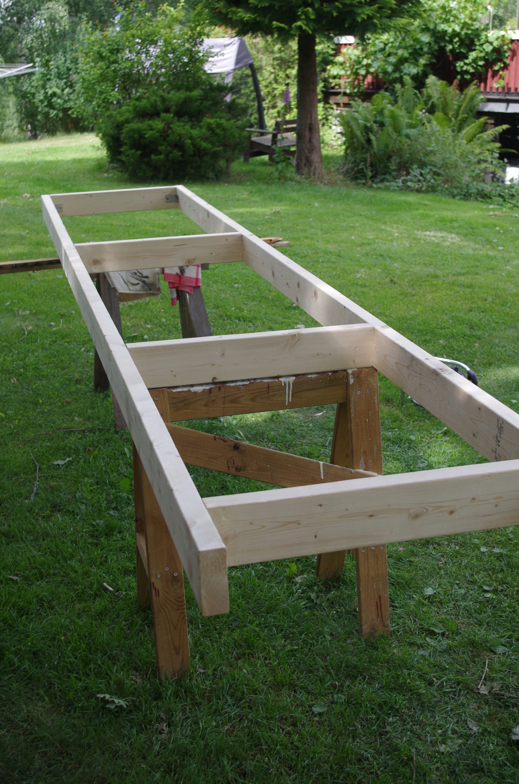
The next thing to build was the strongback which was going to be both a help in getting the correct shape for the stich and glue of the hull and subsequently the cradle and workbench for the hull to rest in when building on it. The crossbraces of the strongback was carefully measured so that the bulkhead sawn-outs would be placed correctly and have some proper support. Since it was quite forcing on the shape of the hull we very carefully levelled it a the place it was going to live in with a water level, e.i. a clear water tube with water in it. This took some time but turned out very well.
Panel plotting
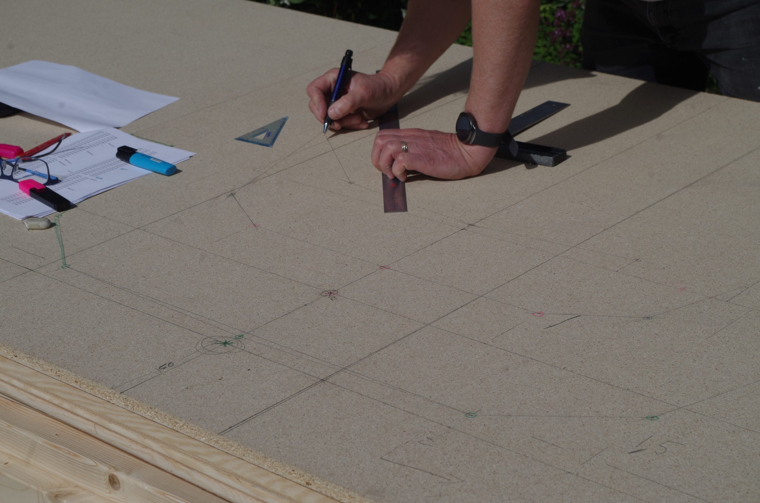
With the plywood glued it was time to start plotting a coordinate system so that the nearly 348 points could be plotted to get the correct hull panels. The coordinate system was created with marking string so that the lines would be perfectly straight. After that the plotting began. It was a very tedious 3 or 4 hours with my uncle reading numbers and me lying on the plywood with rulers marking the points.
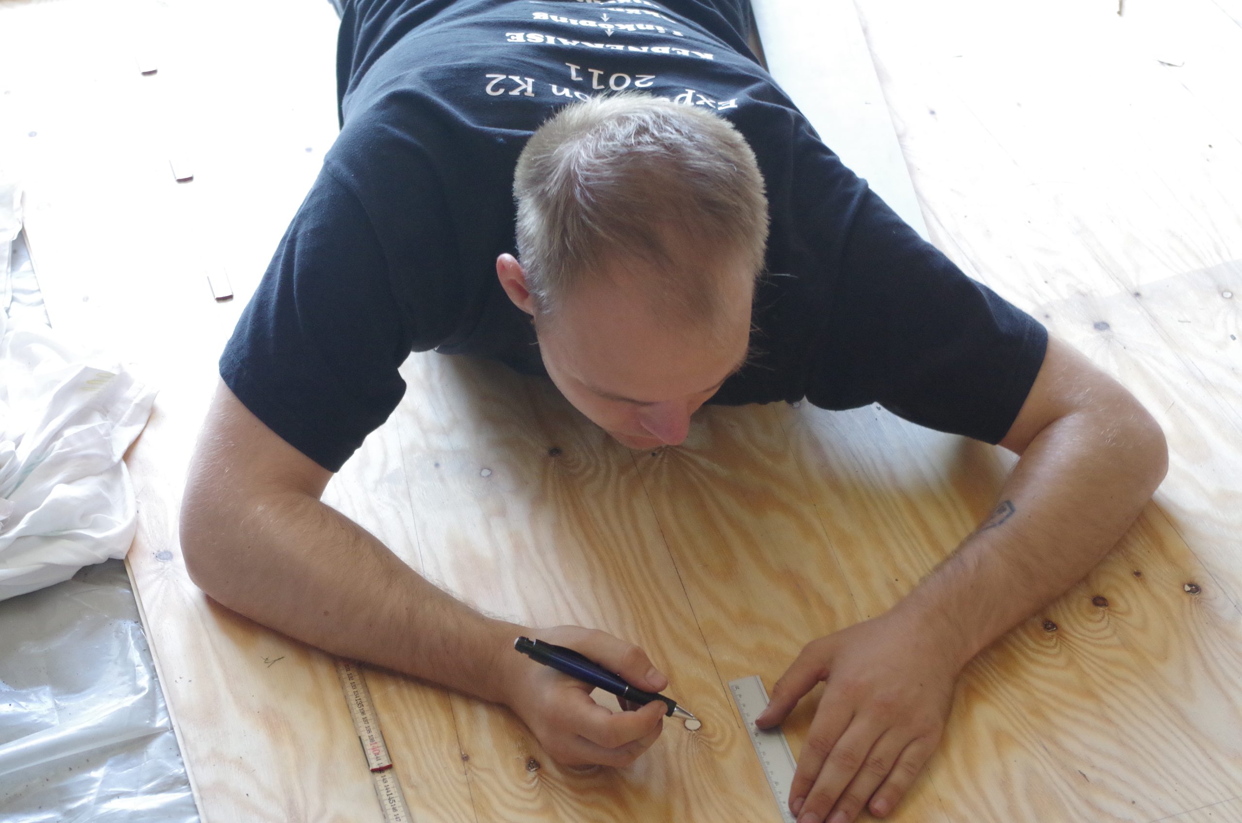

After the plotting was done we split the work. I continued by cutting out the panels while my uncle started plotting and cutting out the bulkhead cutouts that was going to be used on the strongback.
When cutting out the panels I first cut out one side. I then proceeded to clamp that cutout panel to the other side so that an accurate line could be traced. To combat size changes probably made with this method we alternated the pieces when stitching the panels together.

Stitch and glue
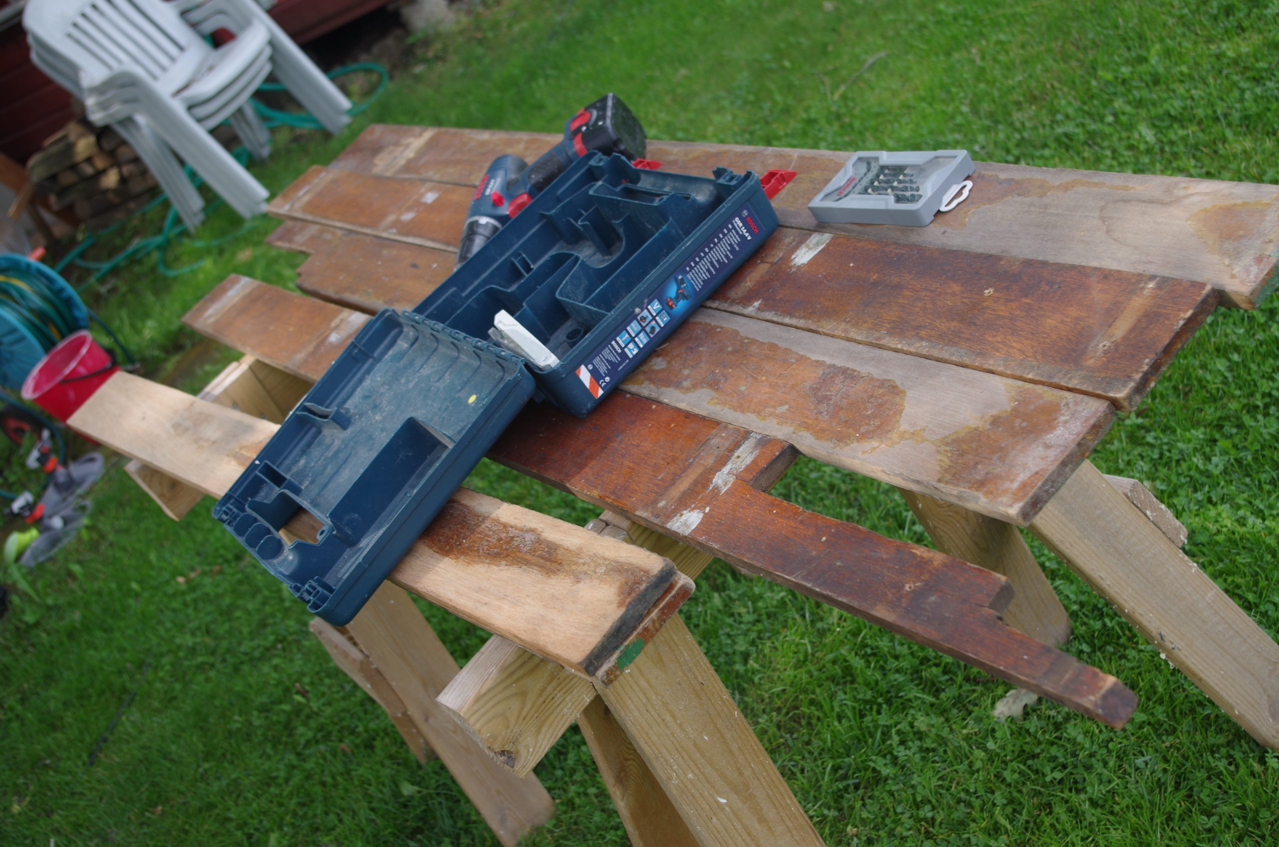
When the panels had been cut out we drilled holes every 10-15 cm or something like that. We could only do this at the bottom without the panels being in the cradle since these are the ones that are both symmetrically similar and are meant be put together. So one of us went with the drill and the other with a fat block of wood to push on the other side of the plywood to avoid tearouts on the backside.
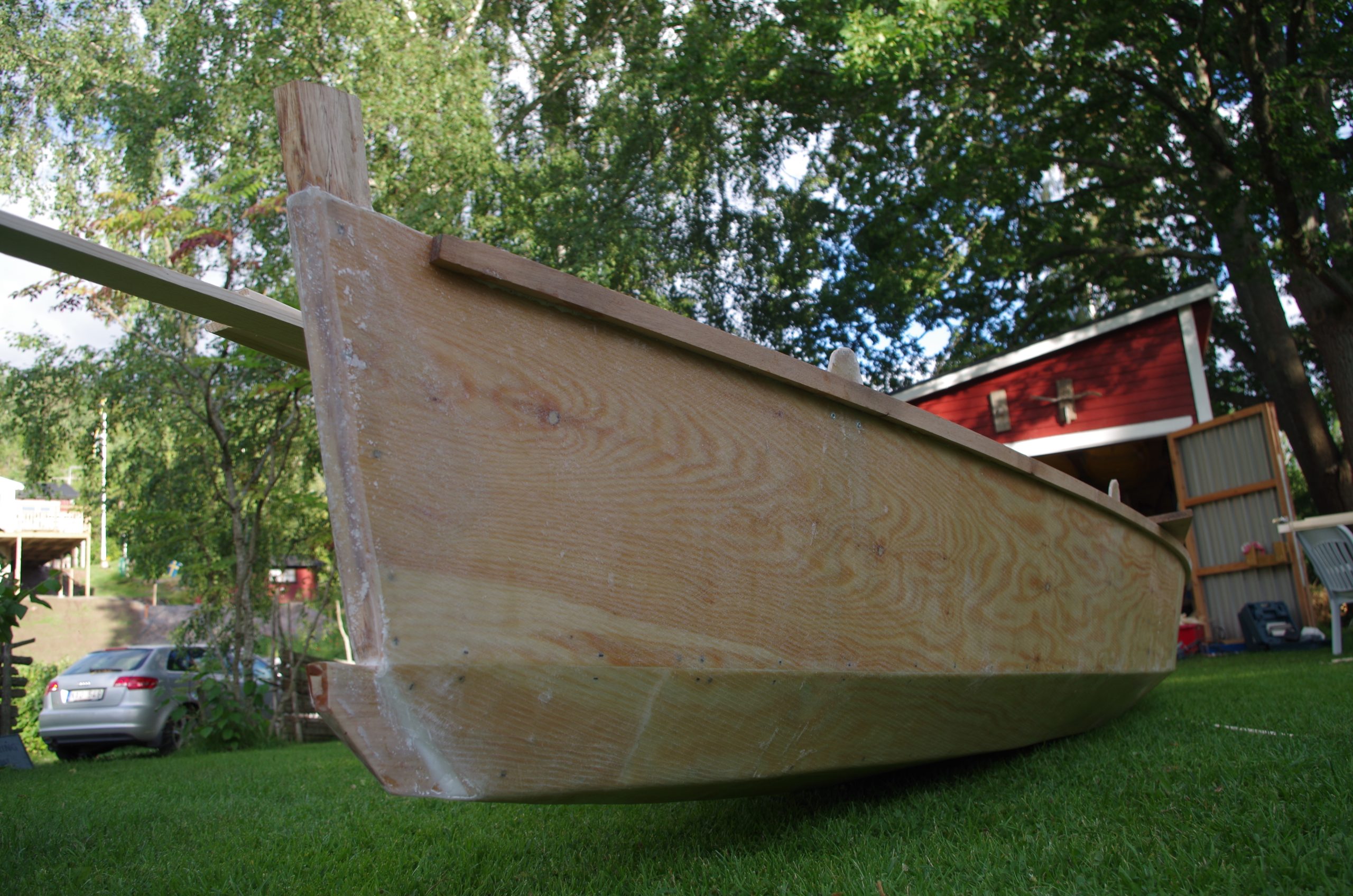
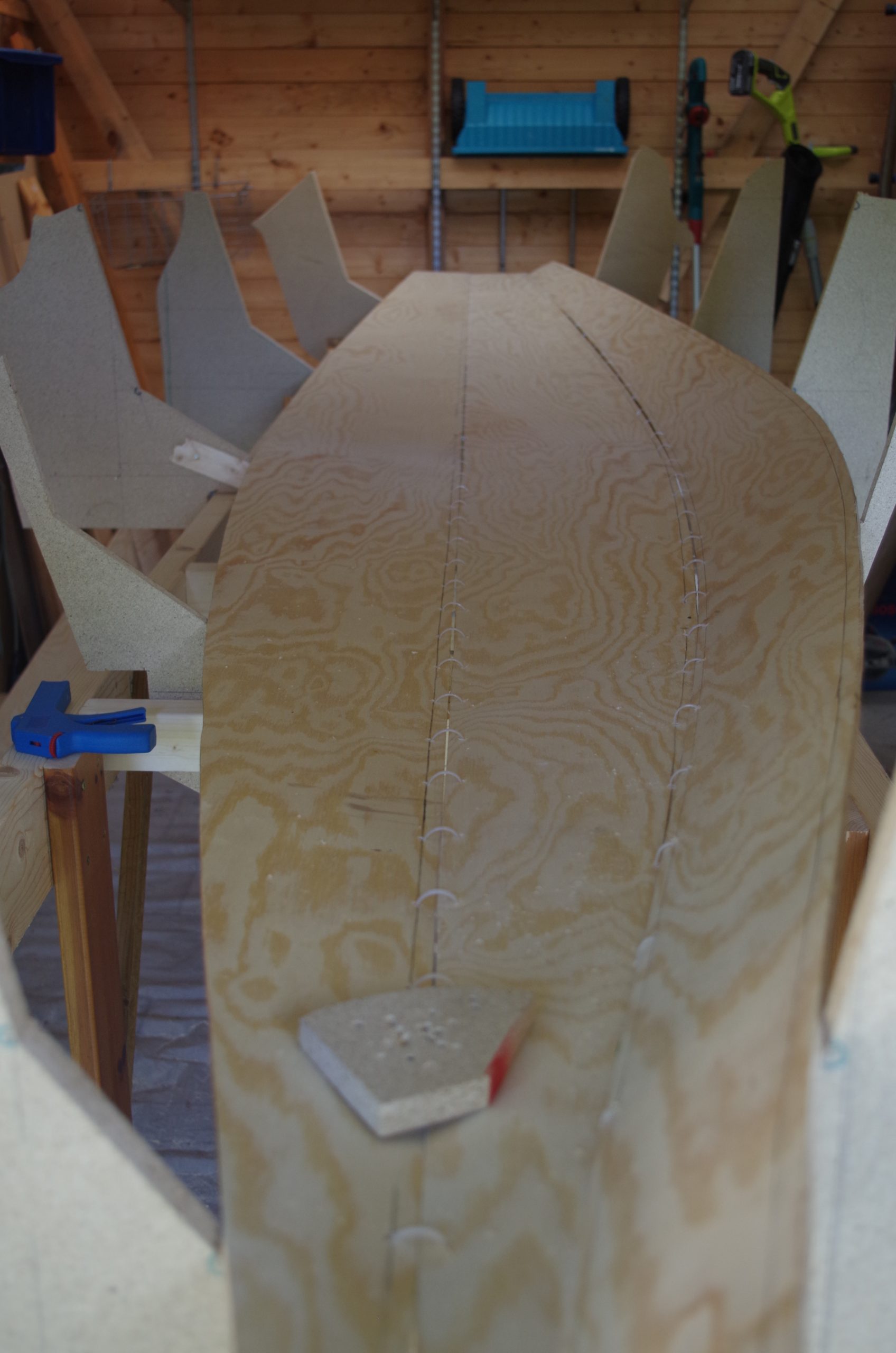
When the holes were drilled it was a simple matter of putting through zip-ties in every hole loosely for all the 300 or something holes. We made sure the heads where on the outside so that they could be cleaned up later. We also had to manufacture a bow piece and a bobstay place of attachment just above the waterline. These to pieces I made from some Oak and maybe Cherry from my uncles wood pile. Too attach the panels to this we used glue and some very big nails during the glue press time. The nails very later removed.

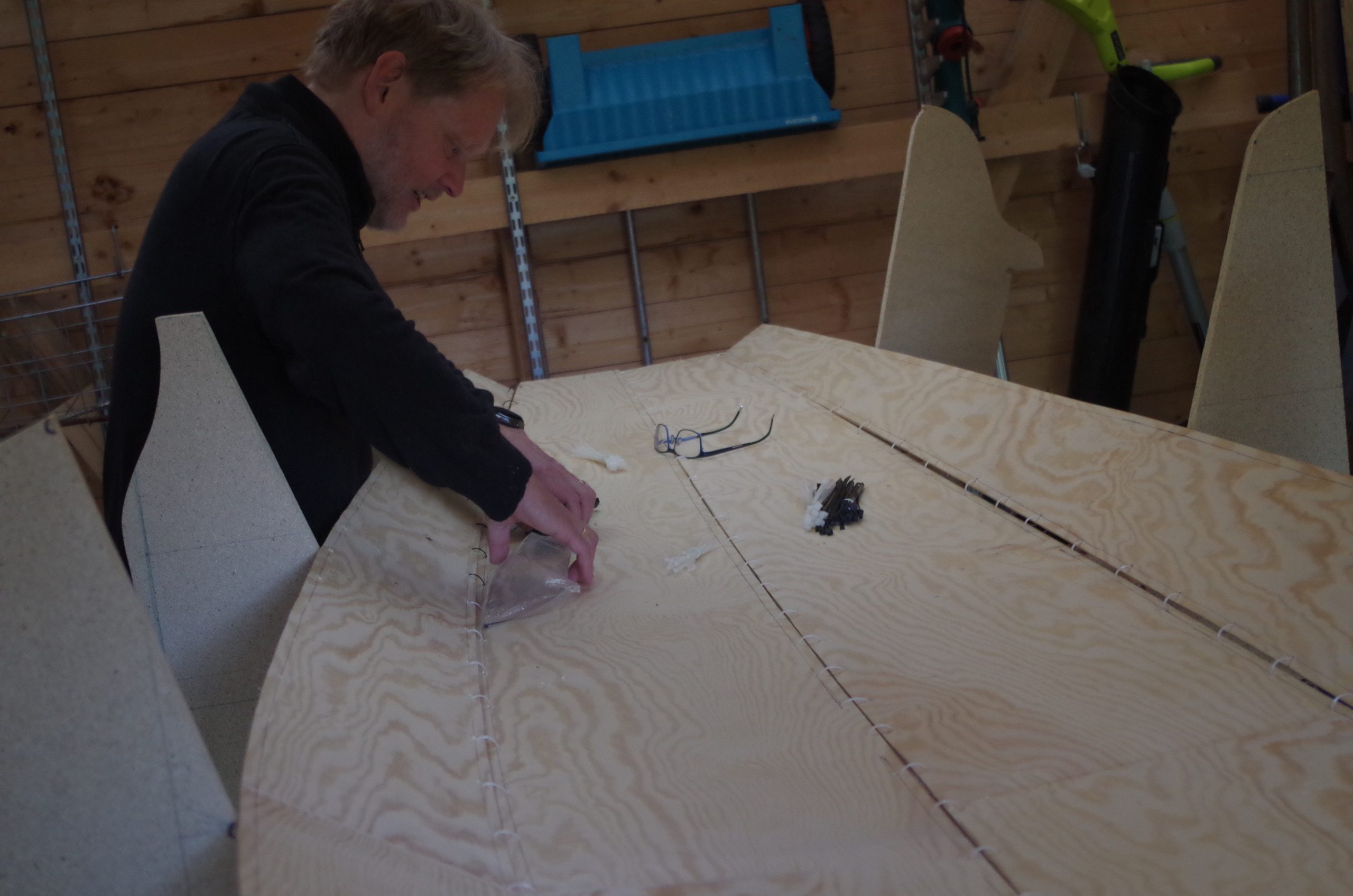
Yes, I did wear newly bought clogs the entire time which ended up leaving semi-permanent marks on my feet. Pro tip is to have socks as well.
When all where loosely fitted we sinched them tight one by one but not all the way directly, it needed adjustment throughout and some we left a little bit loose so that the shape wouldn’t be affected.
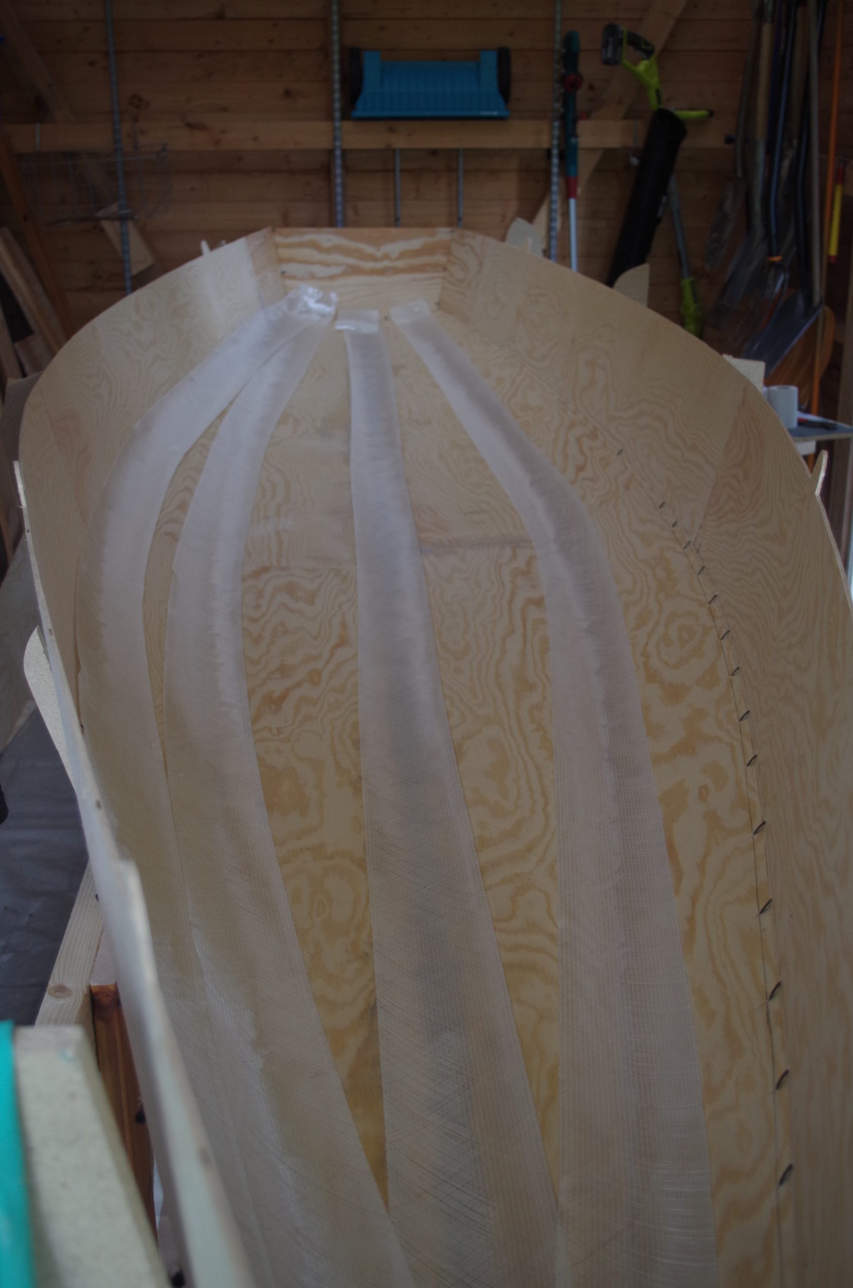
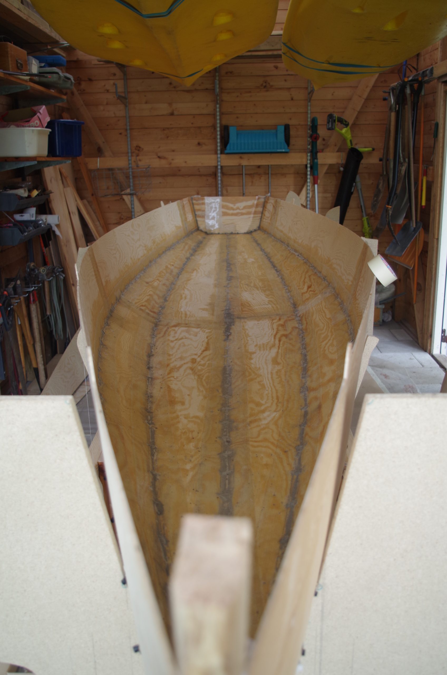
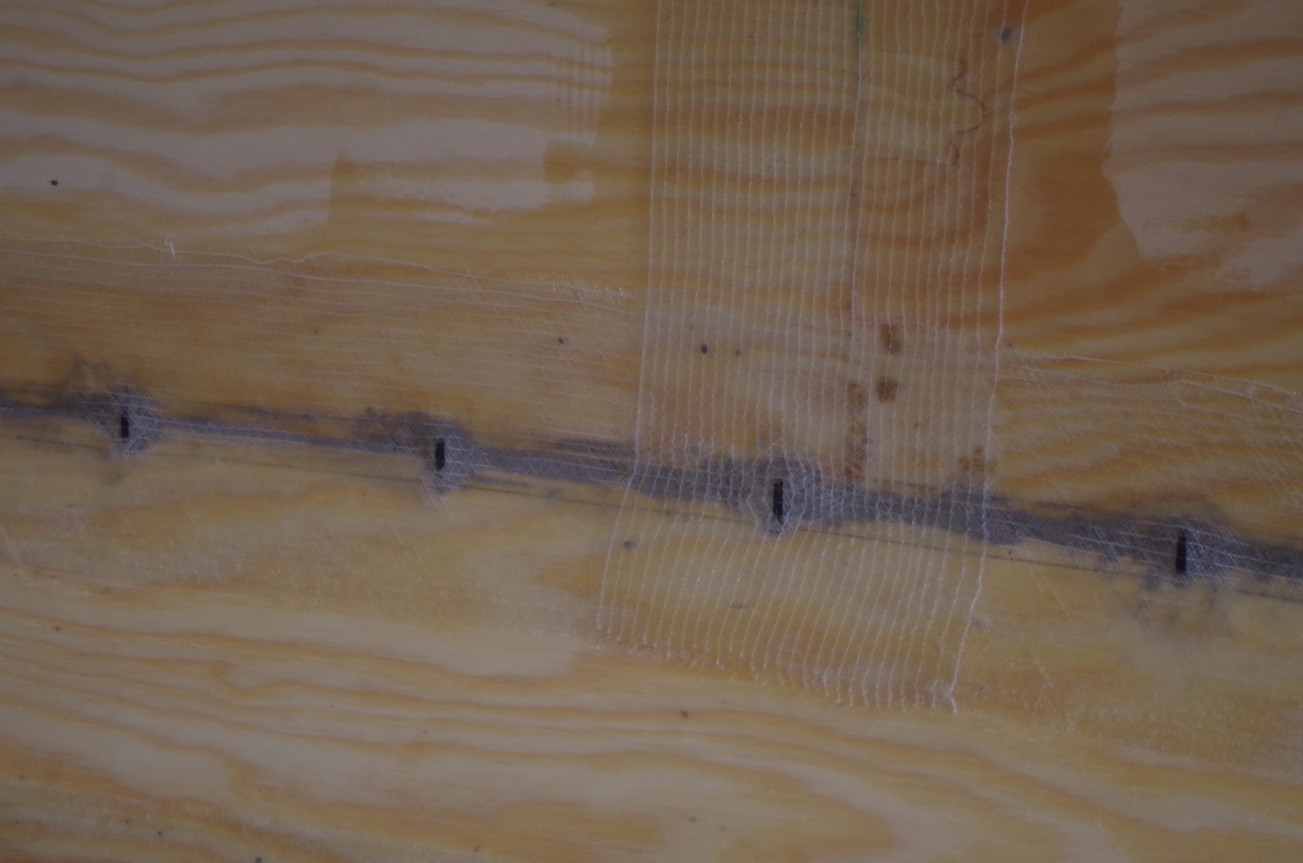
With all the zip-ties suitably tightened we measured out the biaxial glass fibre strips that was going to be used so that we had them ready. The idea was to not the the thickened polyester in the joint kick off to much before laminating the glass fibre so as to achieve the best bond.
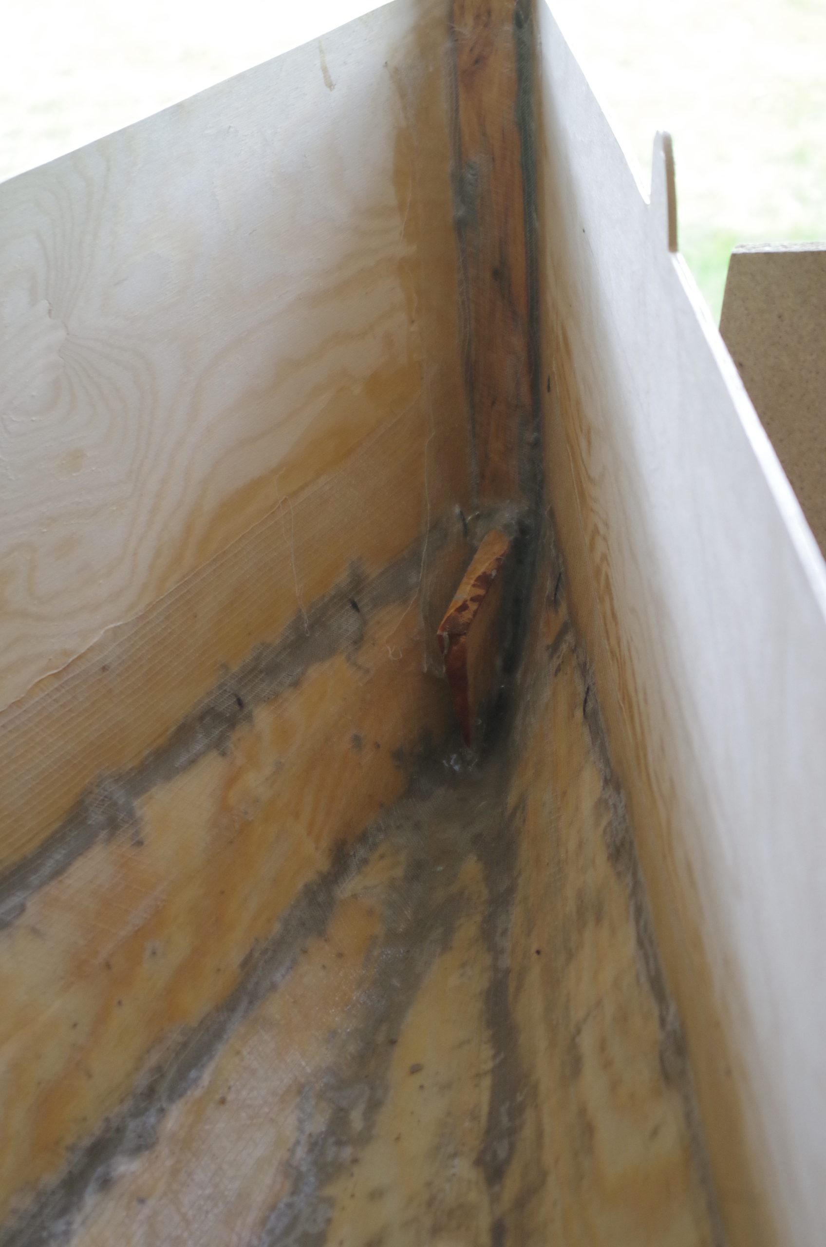
We made thickened polyester and filled all the gaps in the joints, then applied and laminated the glass fibre strips. To keep the weight down we were quite restrictive with the amount of resin, maybe too restrictive, the future will tell.
Stringers and bulkheads
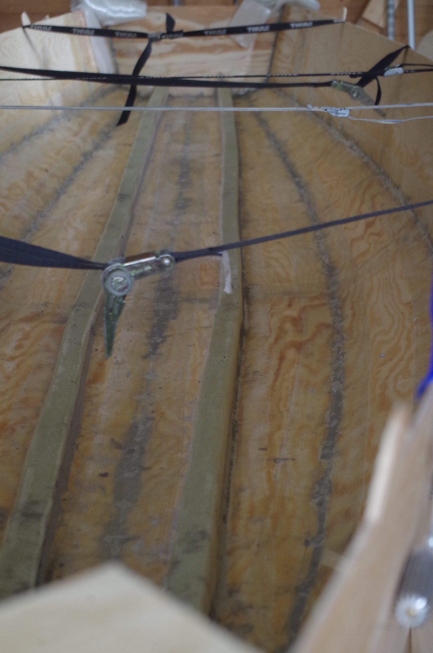
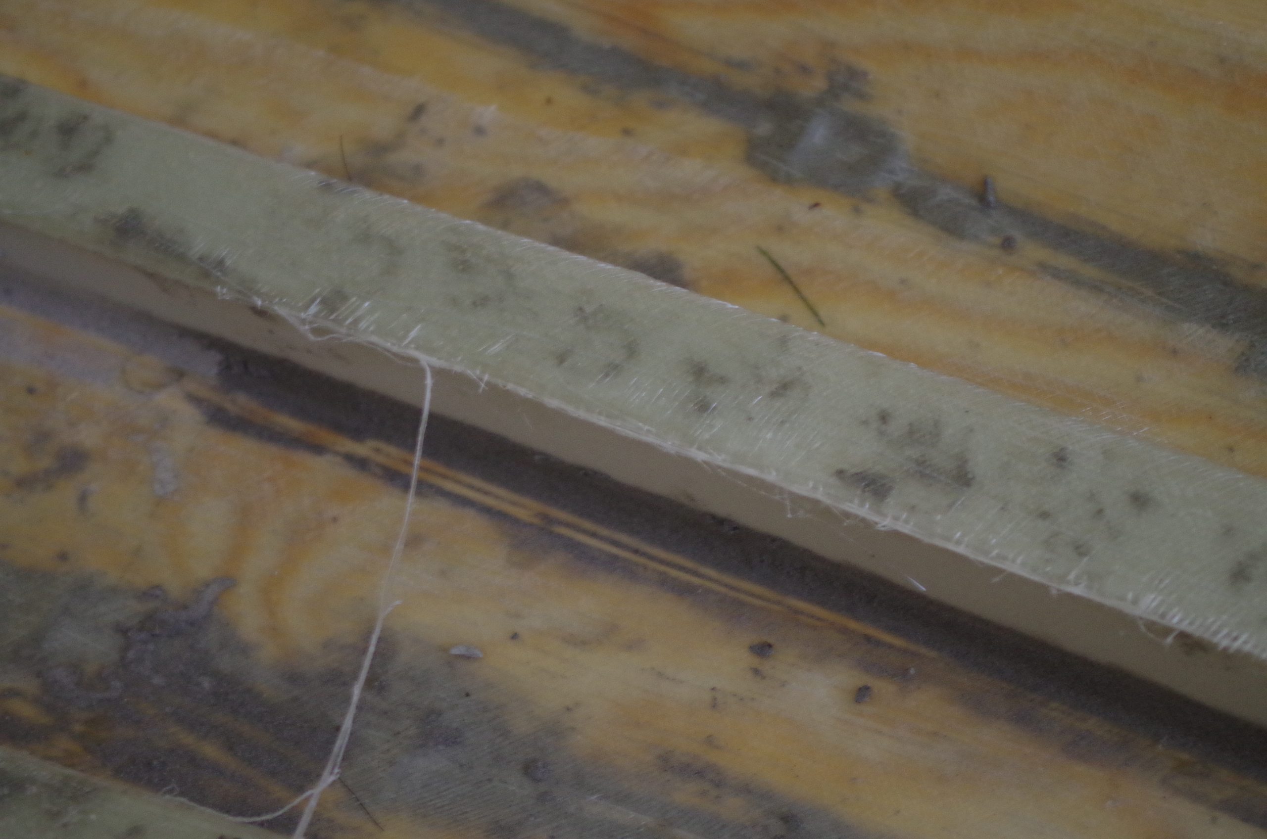
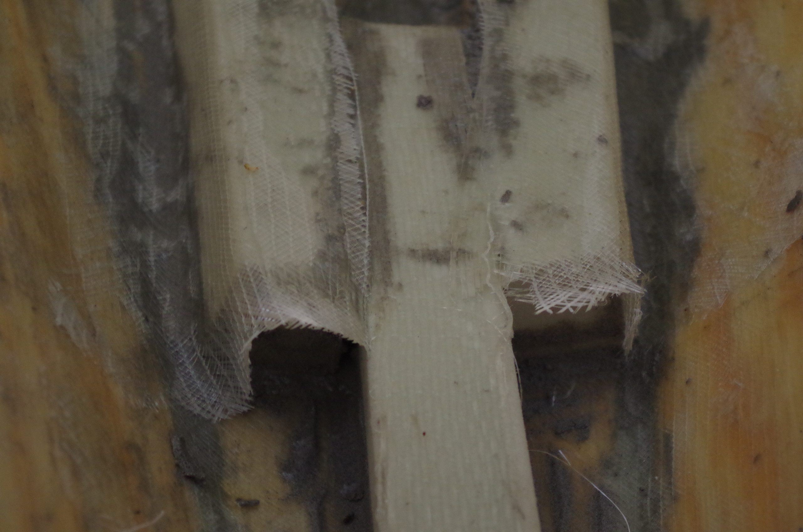
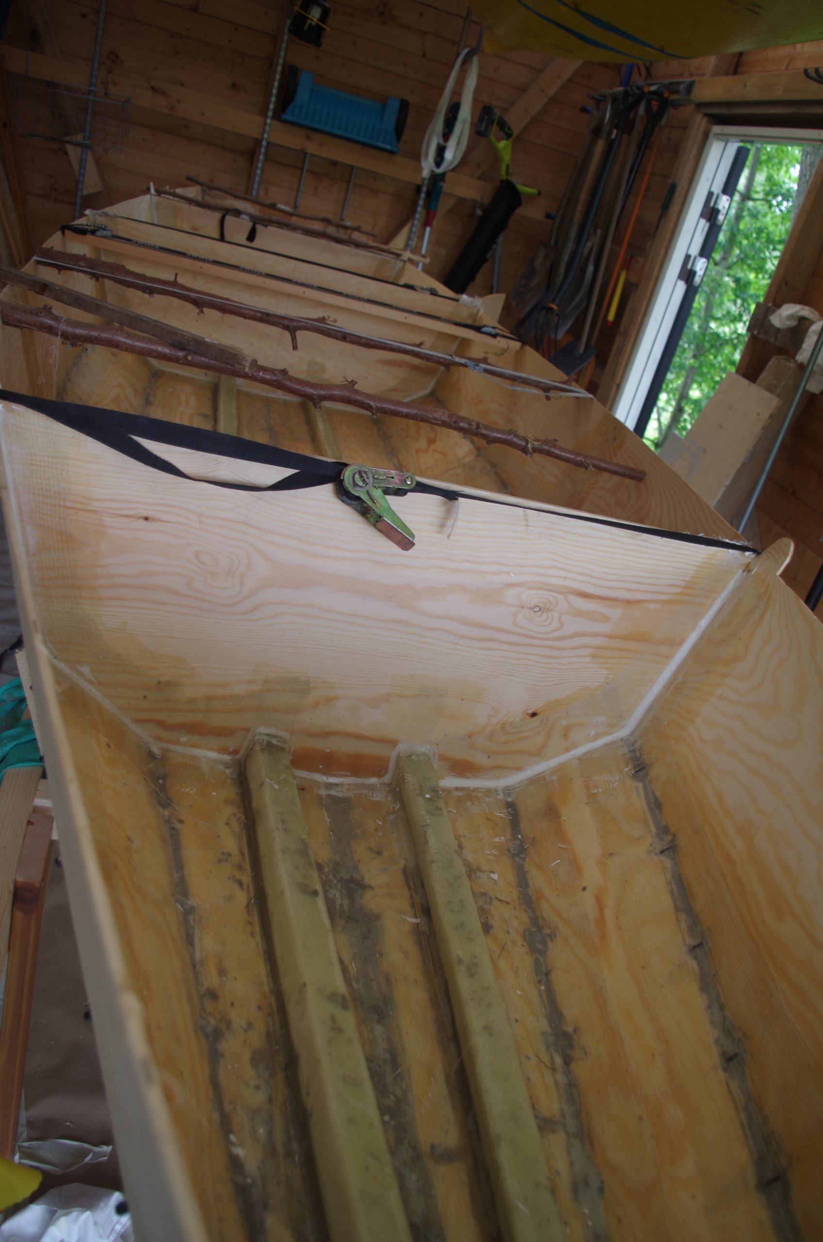
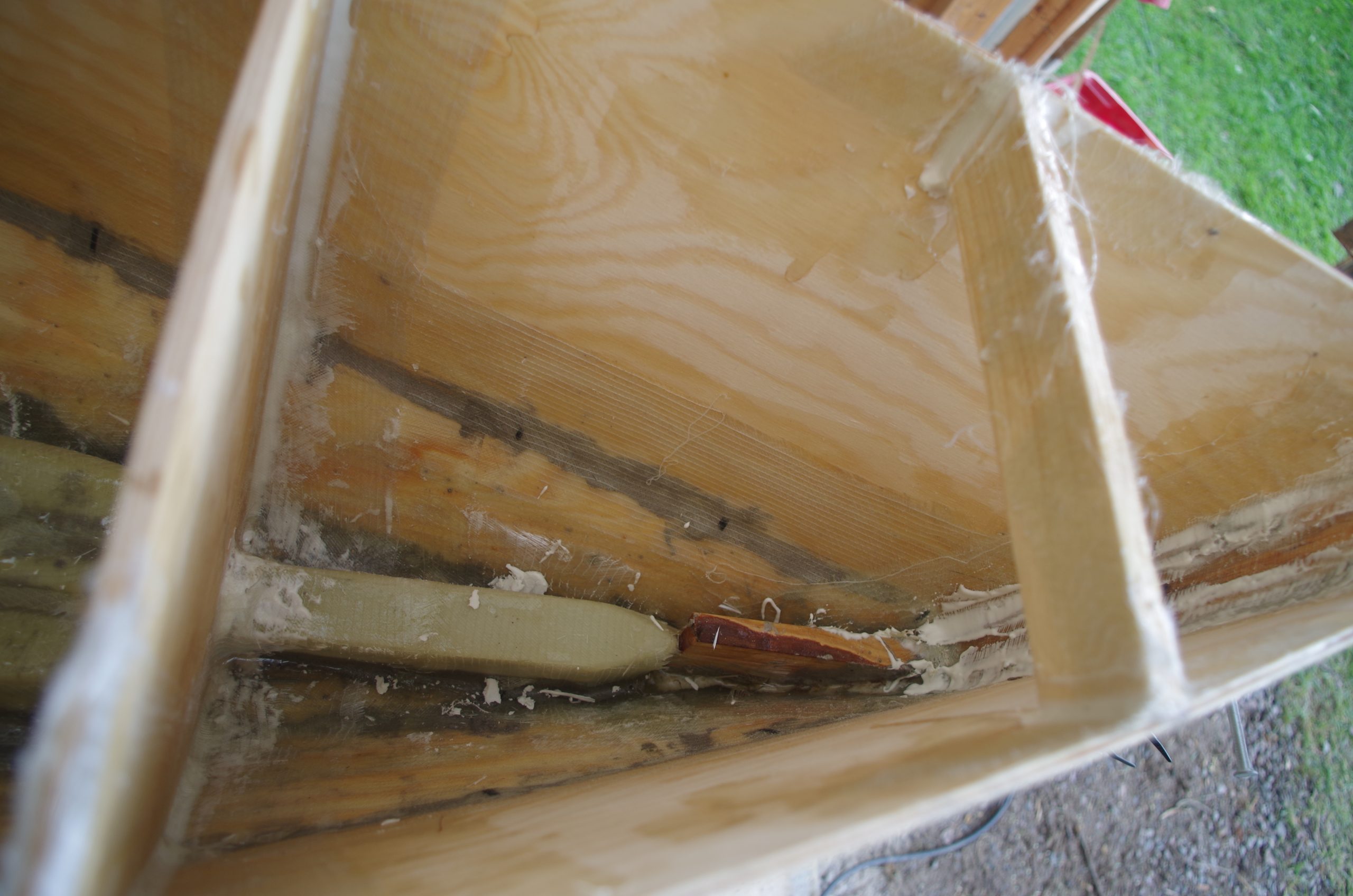
For longitudinal stiffening and to avoid the bottom flexing to much two stringers were built using polyurethane foam core a strip of 600g unidirectional on top then bonded to the hull with the 300g biaxial glass fibre. It was temporarily glued to the wood using ordinary PVA wood glue which didn’t work to well, but we managed to get the thickened polyester corner filler there anyway which stabilised the thing when laying up the glass fibres. We also sanded the top corners of the foam board so that they would be rounded and accept glass fibre more readily. Don’t underdo the sanding on the top, we did and it was a pain to get the biaxial to conform and we did end up getting a lot of air bubbles.
The most front part we did with only a single stringer since the hull is a lot stronger there. At the point of going from two to one we did a big overlap so that the main mast would get a solid foundation to stand on.
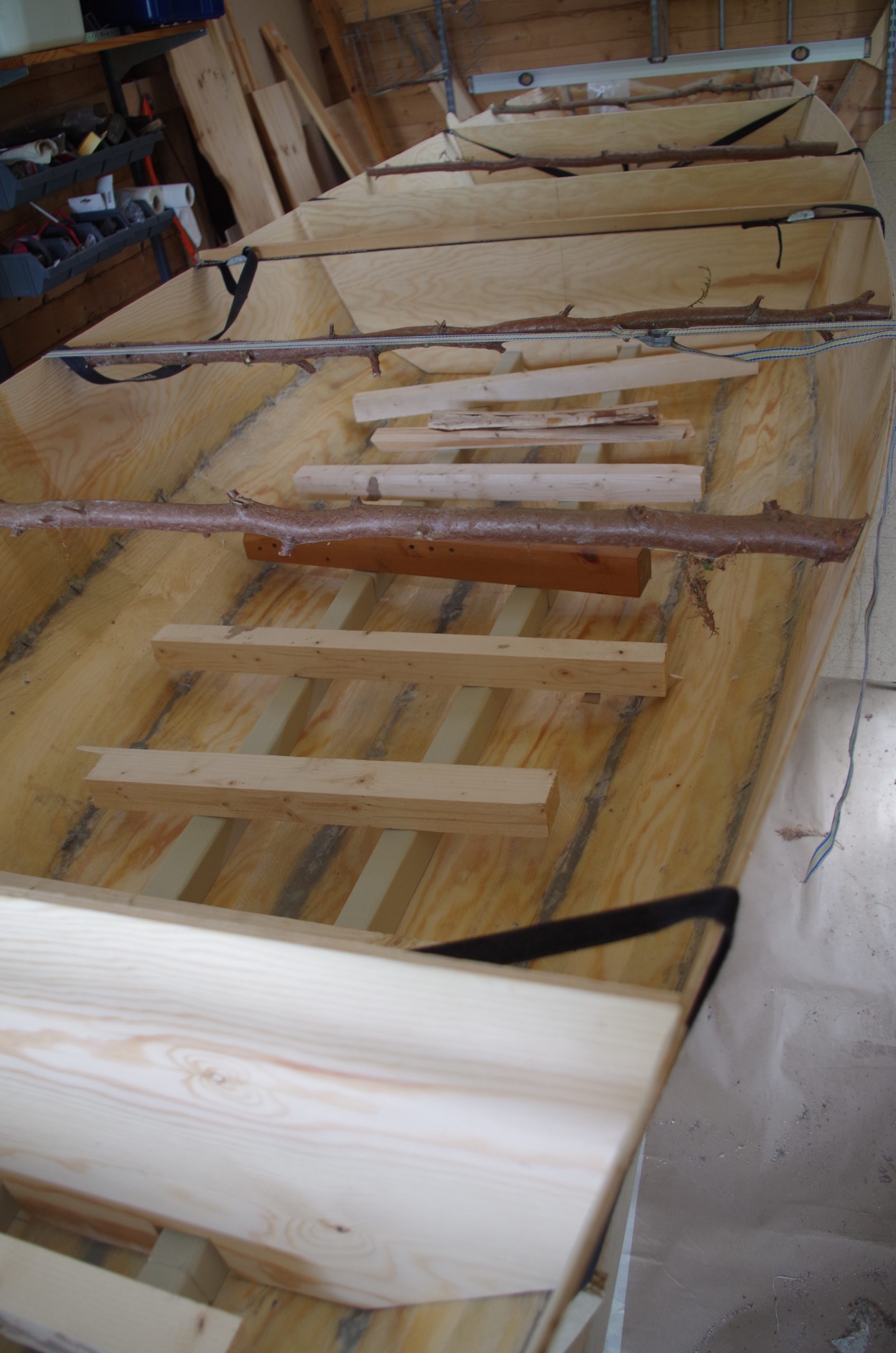
We added the stringers first so that the longitudinal stiffening would be one continuous thing and not broken up by bulkheads. It was a bit trickier to get the bulkheads in their proper places but not to tricky. During the fitting of the bulkheads we used a lot of sticks and some tensioning strips so that we could get the shape of the hull correct.
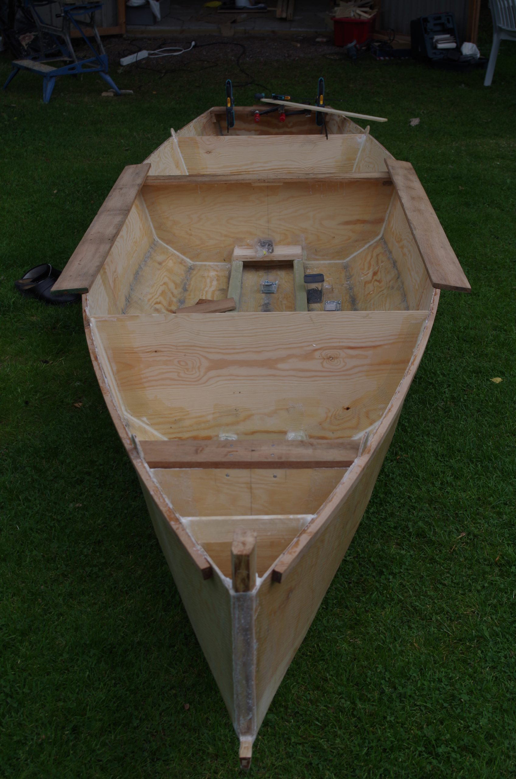
With the stringers glassed in it was time to put the bulkheads in place, fillet the inner corners, and laminated them in place. There are four bulk whole bulkheads at this stage. The first to support the main mast, second to support the hull against mainmast backstay loads, third to support the mizzen, and fourth to support the mizzen backstay.
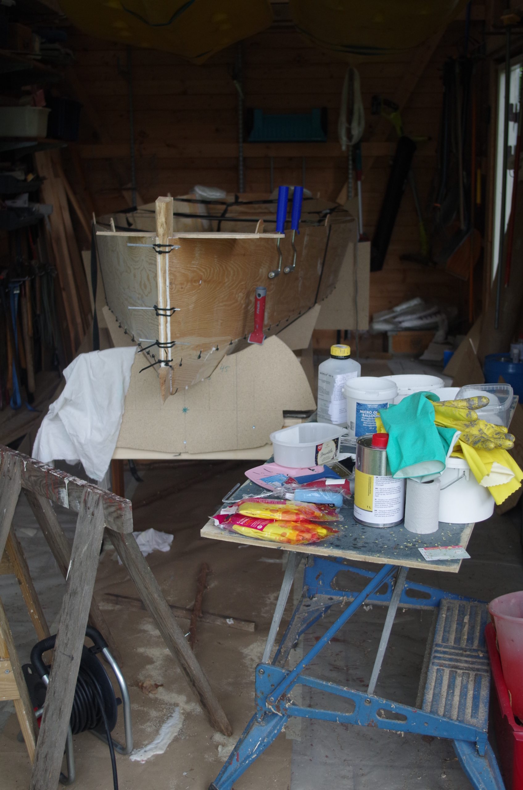
The bow got some very ugly reinforcement with some various improvised methods during the process. The bobstay cherry piece for example got tied in to the longitudinal stringer.
Mast building
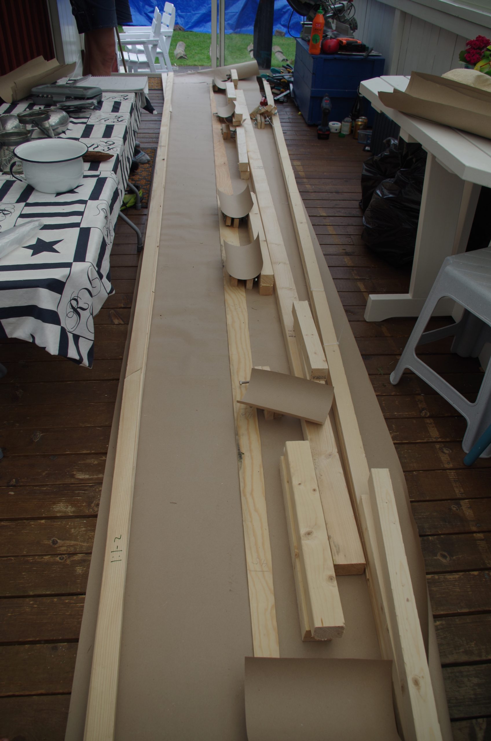
Since I didn’t manage to get hold of some second hand spars from optimists, we had to build our own. So from the kind of knotty spruce that we bought we used a circular saw to saw out 1 cm wide strips which we then sorted according to quality. We then tried to find as many good full-length ones as possible but still had to do some joints, which didn’t turn out very well due to the difficulty of laminating together 5 layers of 5 meter long planks with polyurethane glue. The glue we used had to be clamped down within 5 min so time was precious and we didn’t get it completely right.
We clamped one of the masts with a lot of manual clamps, made from bolts and small bits of wood. The other one we actually had proper clamps for. I can only recommend spending more time than you think on making masts if you have to. To get them nice.
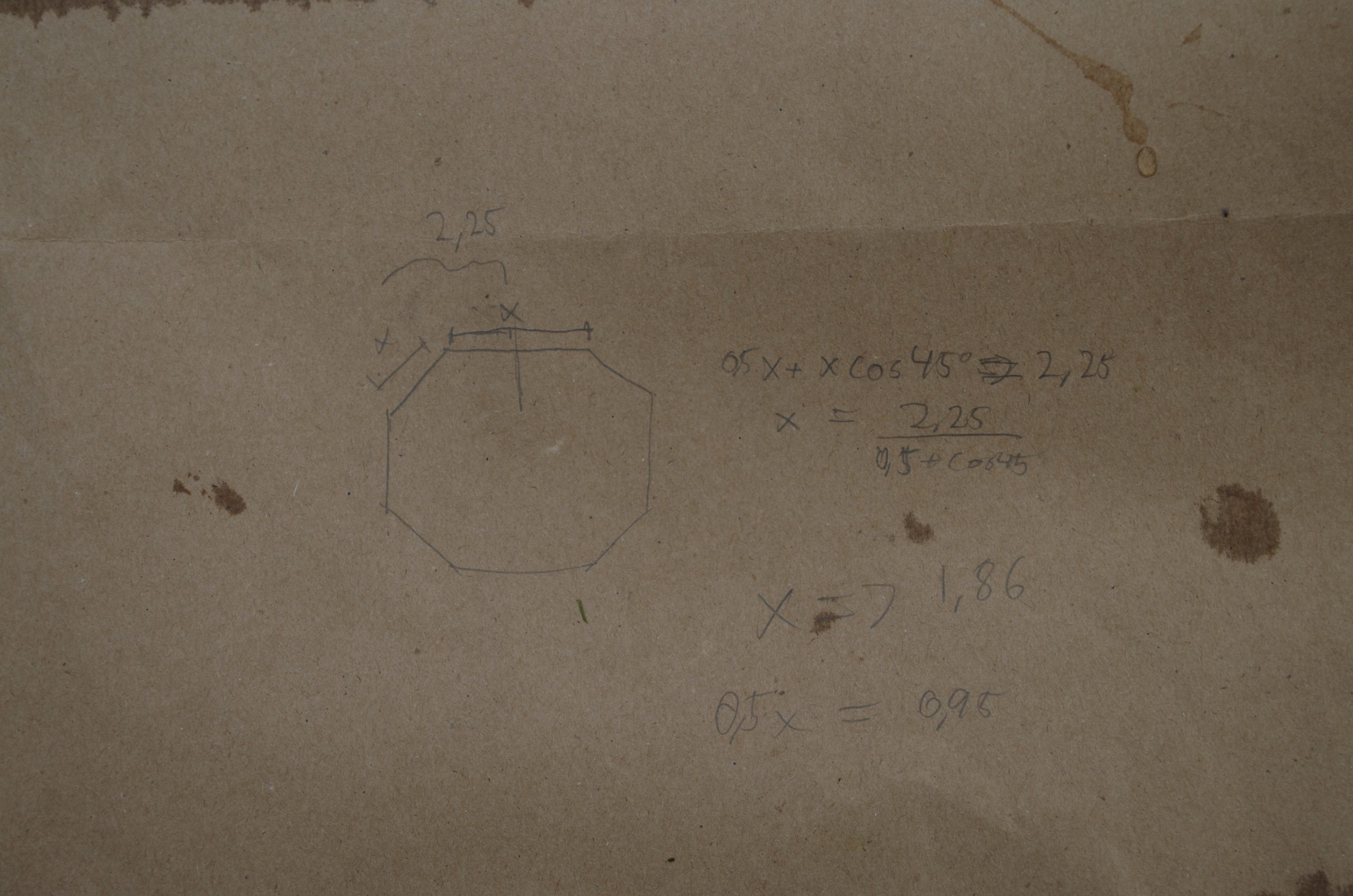
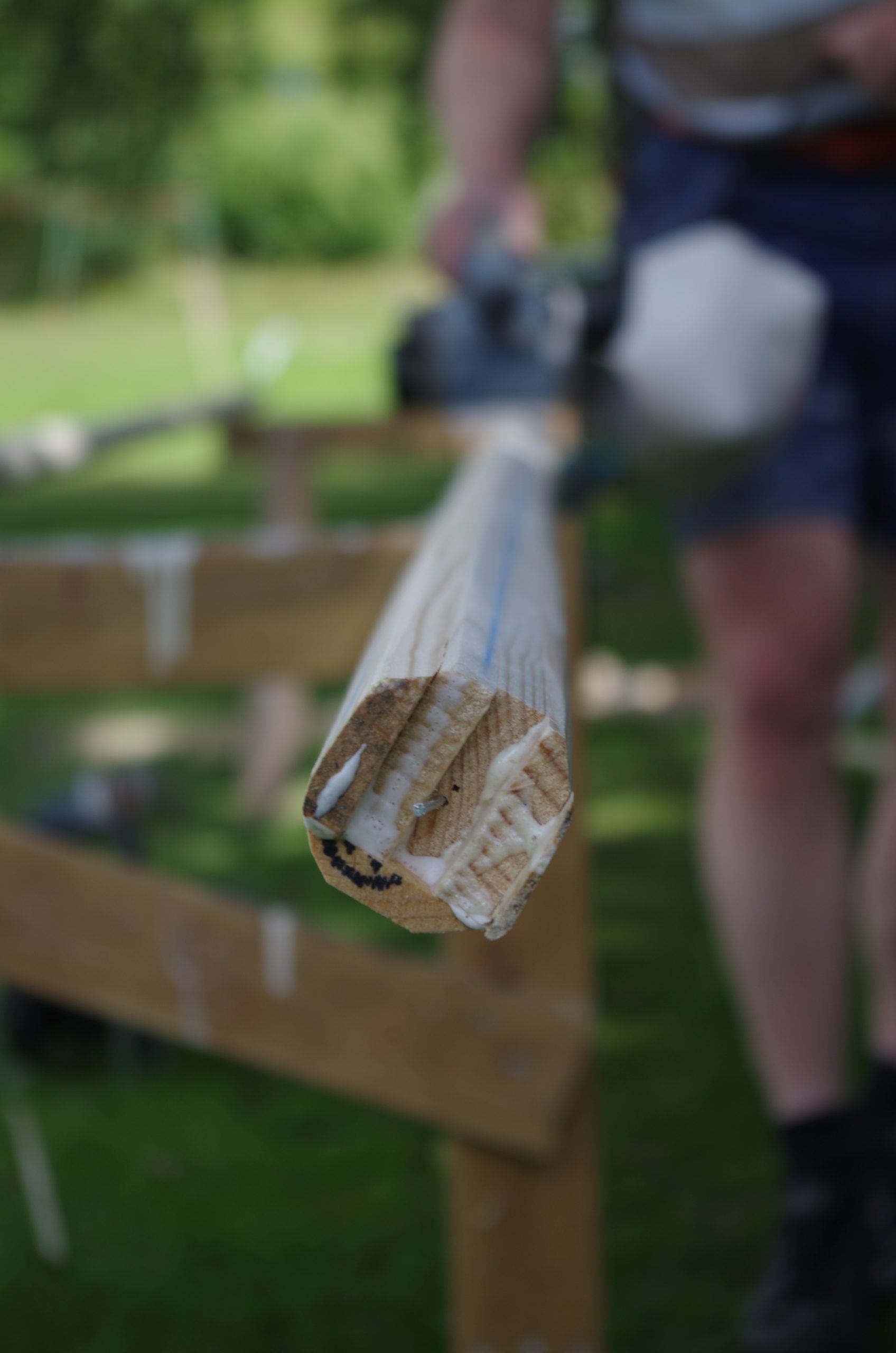
Whenever we had some time to spare in between all the laminating we then proceeded to plane away on the masts to get them round and straight. First to and octagon and then hexadecagon in crosssection before sanding them round, all the time checking for straightness.
Turnover time
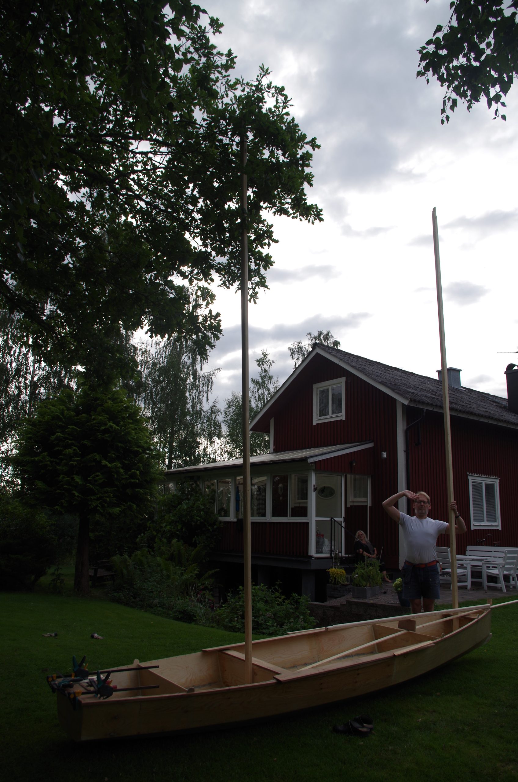
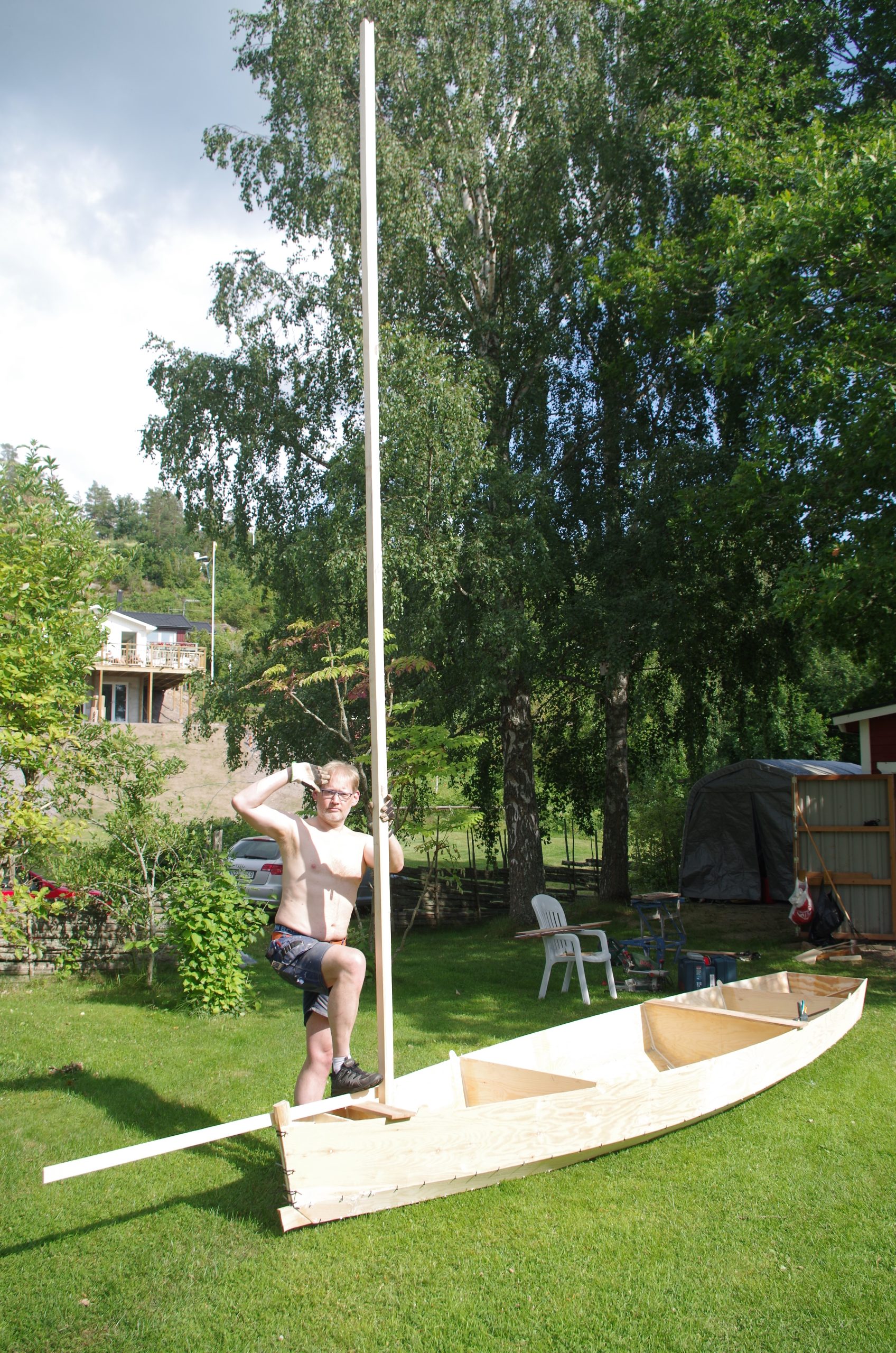
With the polyester properly cured it was time to turn the hull over and begin work on the outside. We couldn’t resist looking at how the mast and bowsprit might look and proceeded on taking a photograph. Looks quite nice!
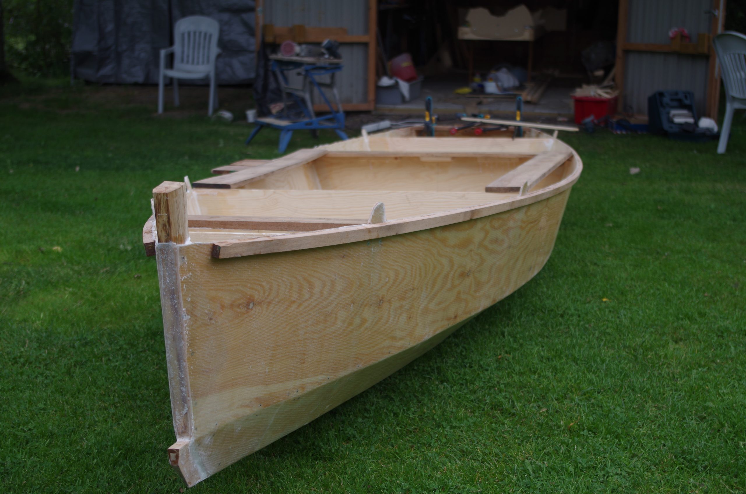
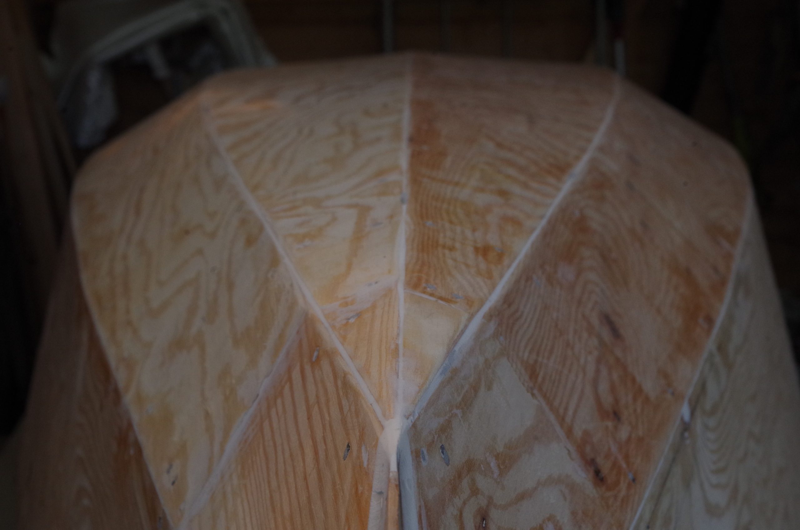
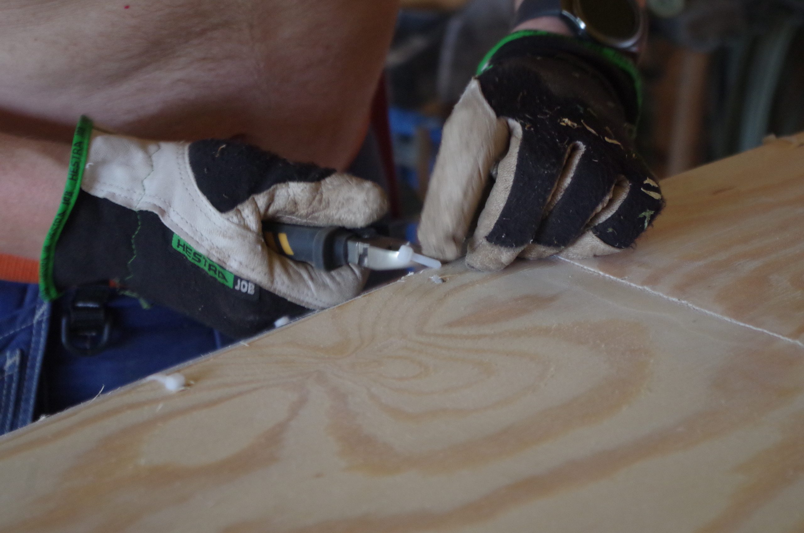
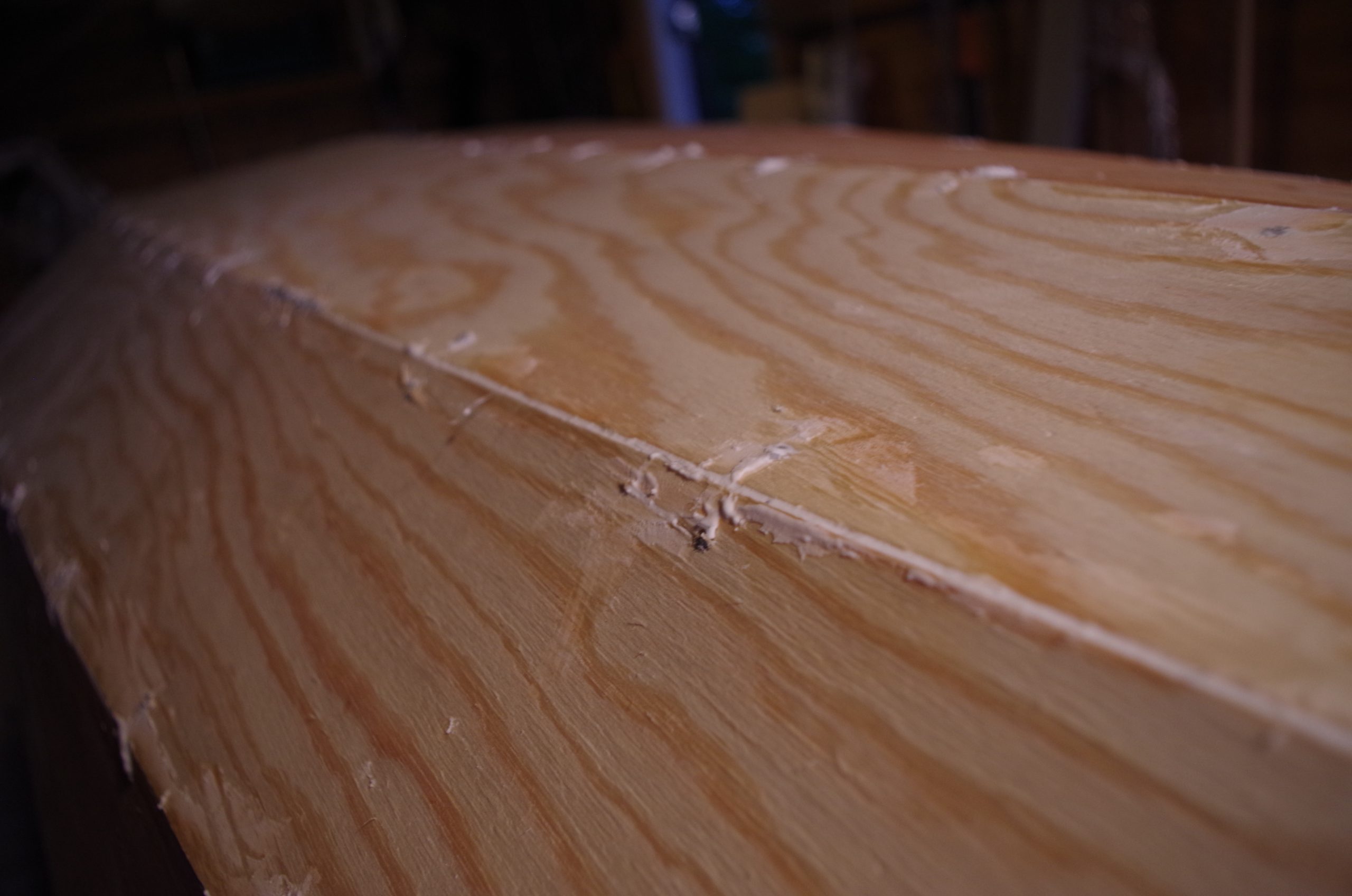
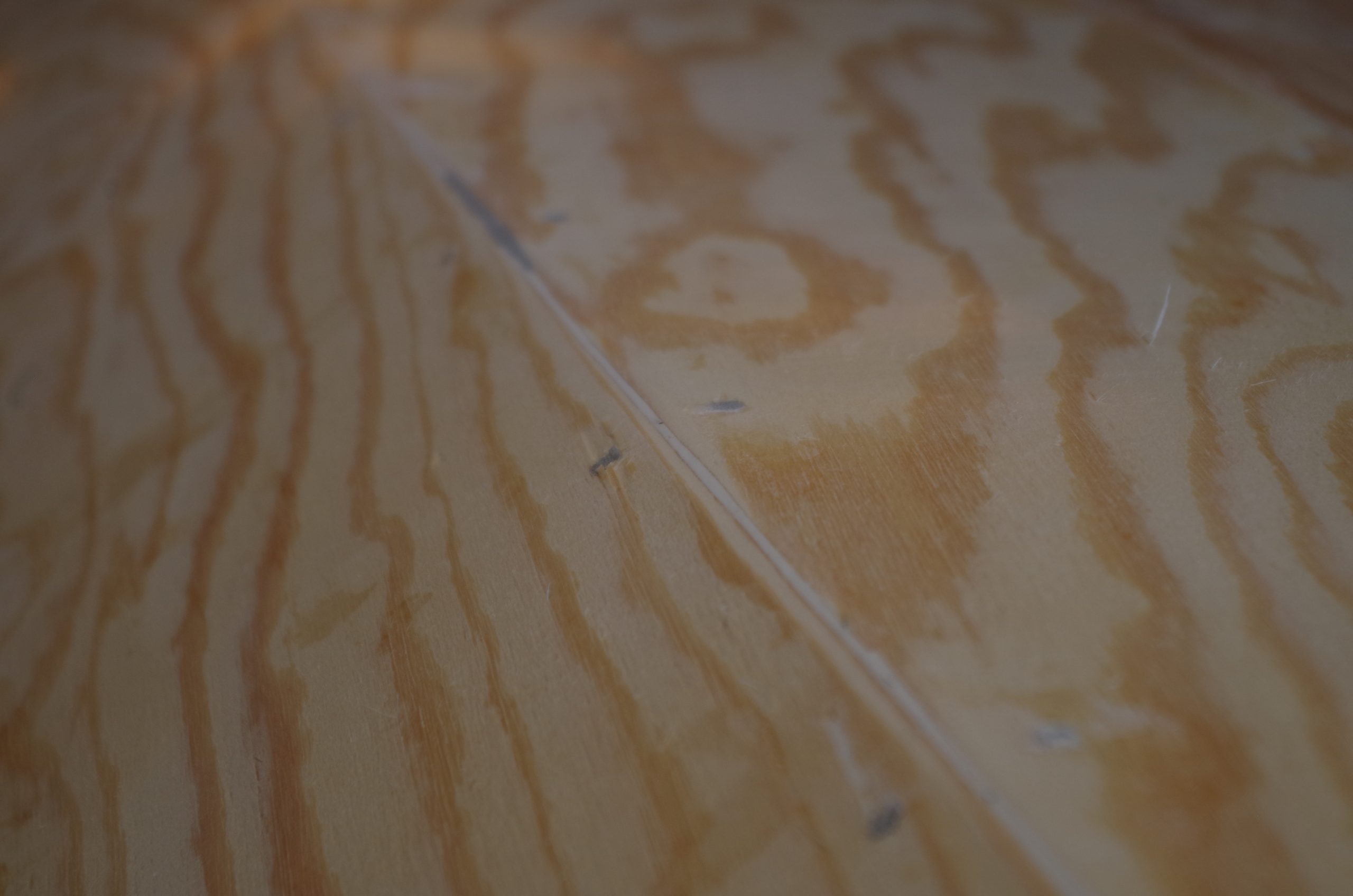
We disassembled the sawnout bulkheads from the strongback and put the hull back on it but now upside down. The next task was to remove all the visible parts of the zip-ties from the outside, add fillet to the joints and sand of and fair the joints in preparation for the 3 layers of glassfibre that was going on the outside. The shape of the hull was starting to look really good with the fillet lines accentuating the shape.
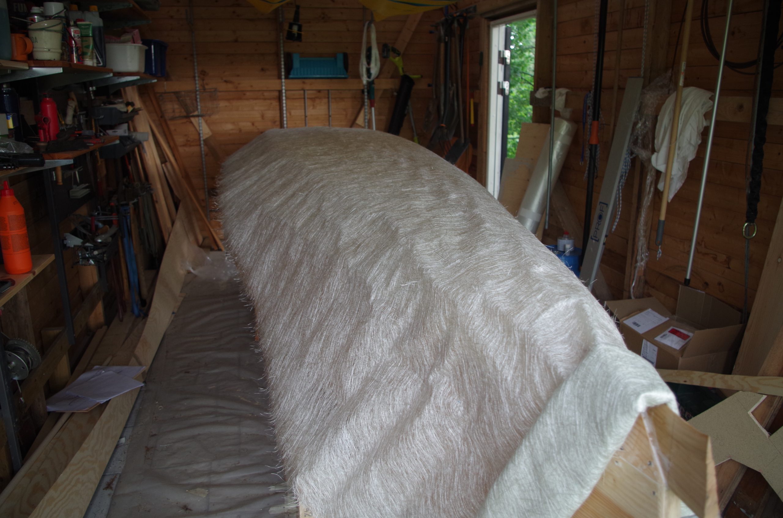
We measured and cut out all of the fibreglass layers, first 300g biaxial, then 300g chopped strand, then 300g biaxial. This to make sure that we could keep a high pace and get all of the layers chemically bonded to each other, and also minimise the amount of resin used to keep the weight down.
Laminating the outside
Well, there isn’t to much to say about this. Armed with rollers, aluminium rollers, and scissors; protected by space suits and respiratory equipment we went about it.
To not have the polyester go of to much between the layers we had to work very quickly. The forst layer of biaxial went on quite quickly and we managed to get it mostly without air bubbles.
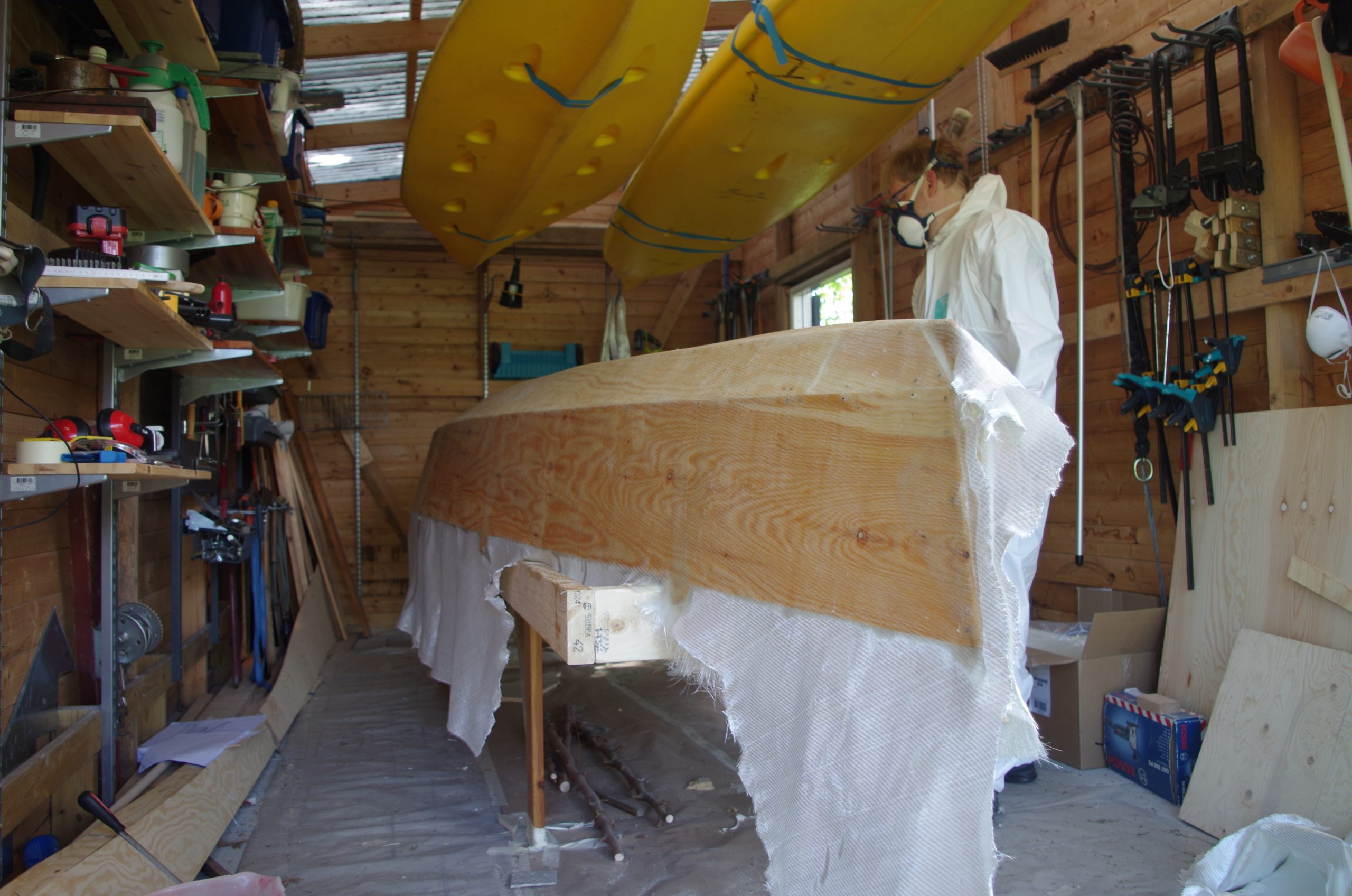

The second layer, the chopped strand, went on easy enough since when we the binding dissolves and the fibres can move about quite freely. However, the last layer of the biaxial wa quite tricky because it kind of stuck a little to the layers underneath and we got some mayor air bubbles that we never managed to sort out. We had been doing this for a couple of hours now, it was already dark outside (like 11 pm, summer in Sweded), we were knackered so we went to bed. The next day we removed the air-bubbles by sanding and added patches of chopped strand to build up the thickness again.
Gunwales
I had visited Göteborgs Skeppshandel & Marinskroten (the Gothenburg Ship Changler & Marine Scrap yard) before I left for the build to get some cheap wire for the headstay and blocks for the rigging. I found some old mahogany sole that I decided would be very nice to have on the boat, so I bought it.
It needed some cleaning up to do though: disassemble, removing corroded brass screws, planing flat etc. I don’t think I hit too many unremoved bits of brass with the planer though.
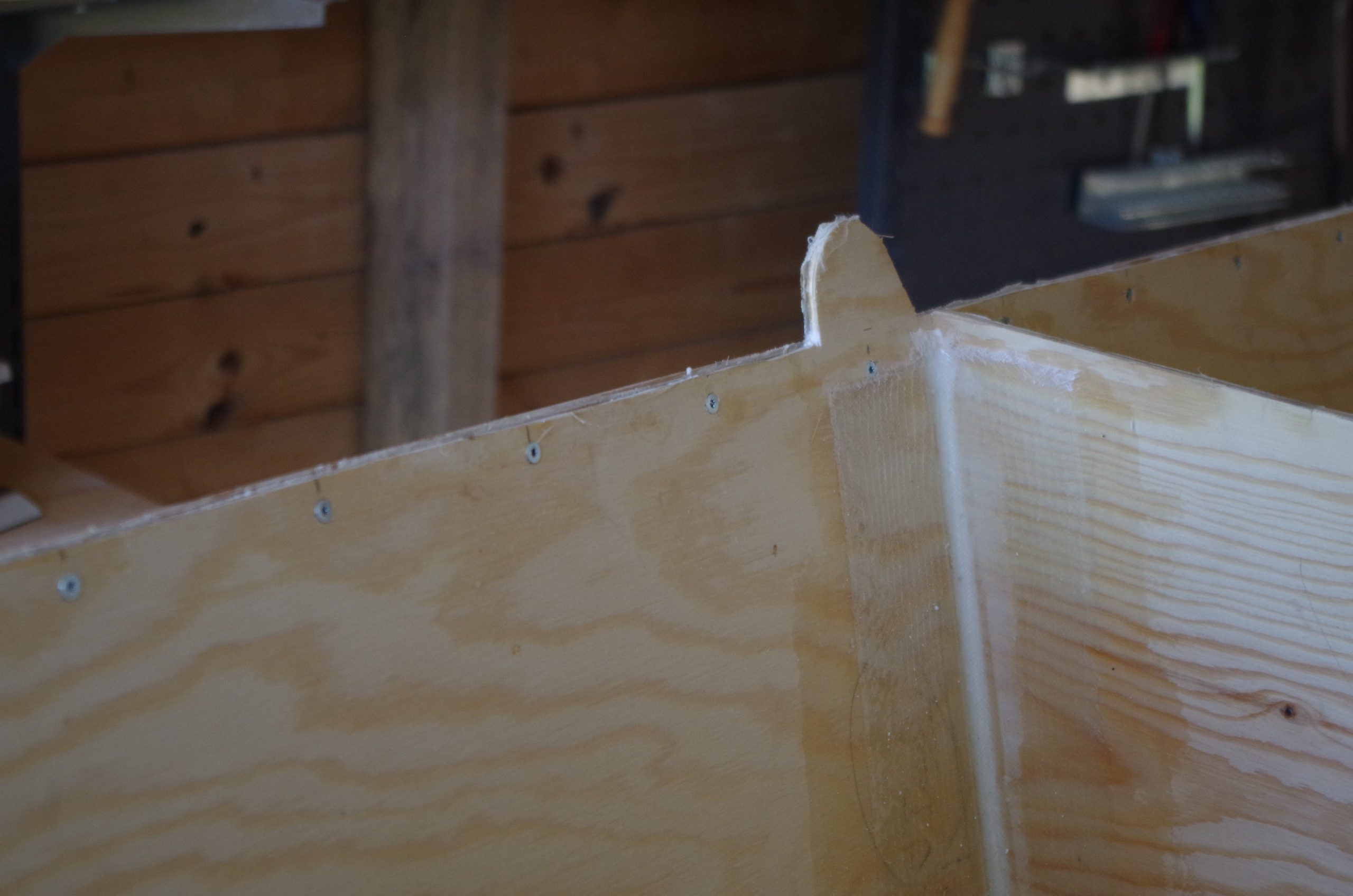
I then sawed some of the planks into strips for the gunwales. To make the sides a little bit stiffer and tougher, to lock the outer laminate in place in case of delamination from the wood, and so that they wouldn’t be directly painful to sit on. The strips were joined with 12:1 joints using polyurethane glue. But the joints had the same problem as the plywood panel’s joints and one of them actually failed when fastening it.
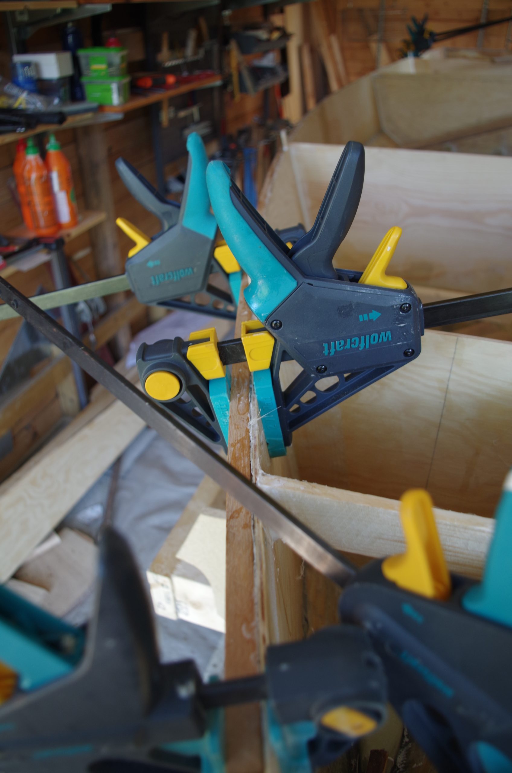
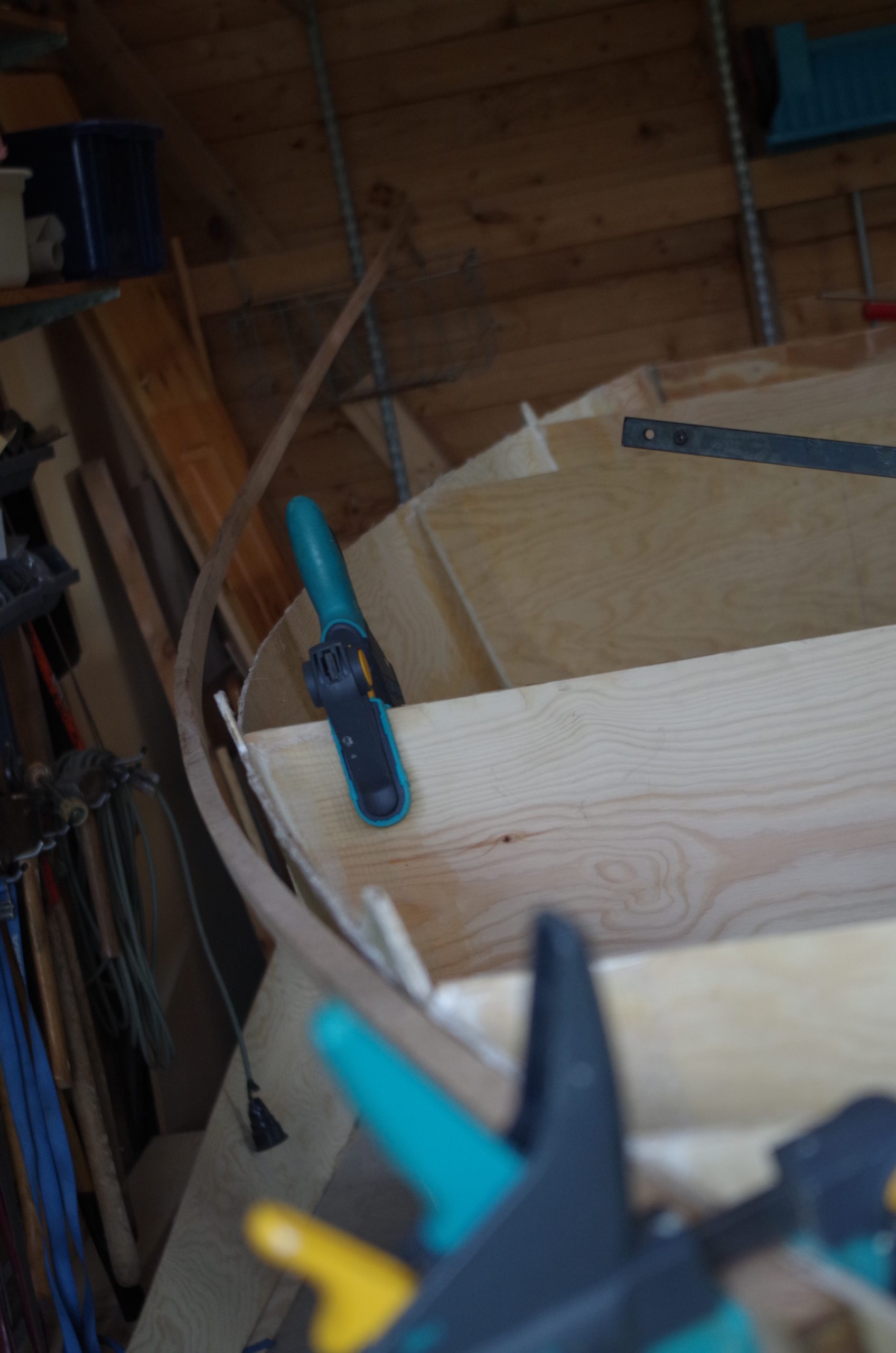
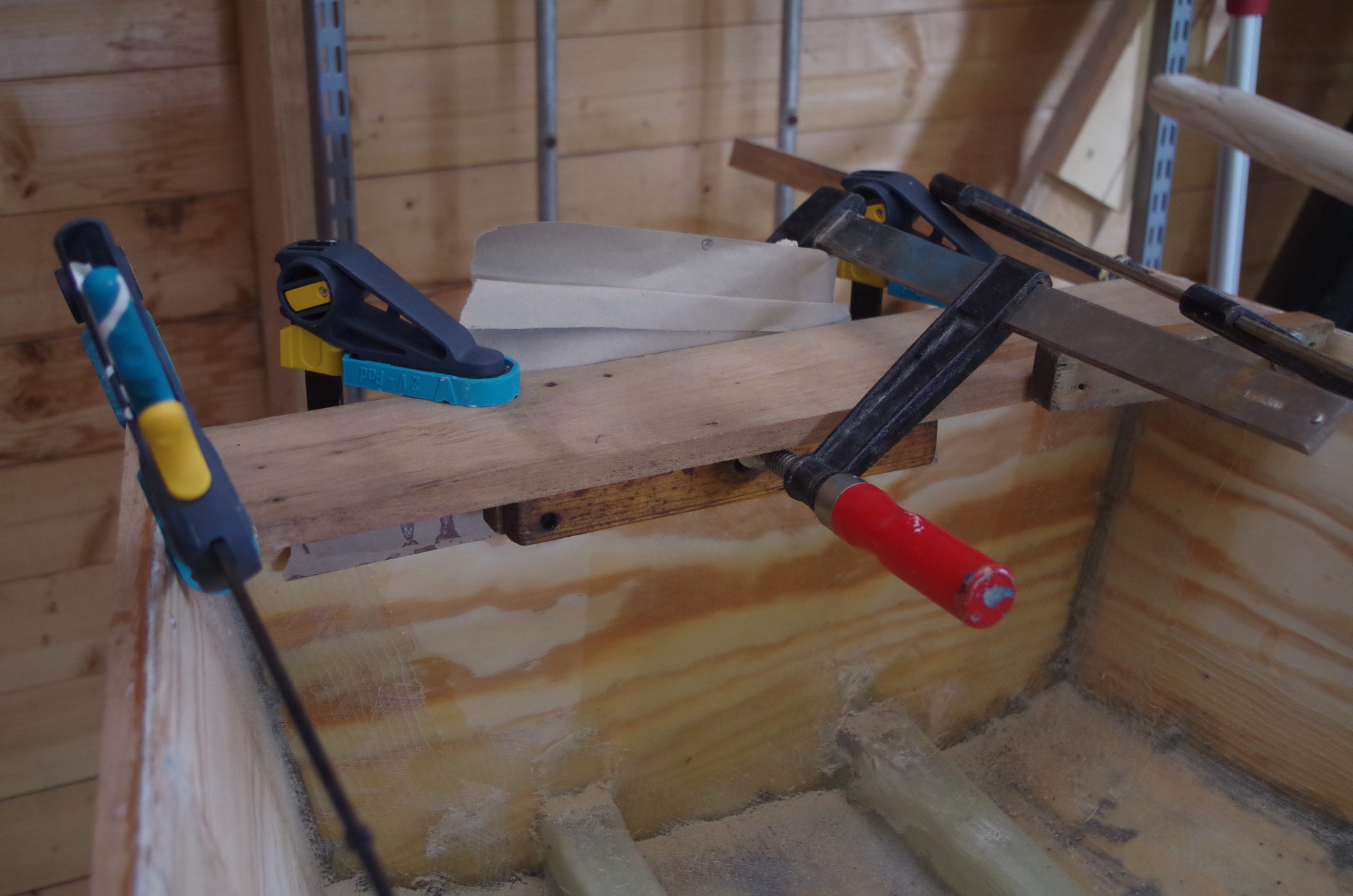
We fastened the gunwale by bit by bit glueing, clamping then screwing from the inside until it was all complete. The broken joint we “fixed” by clamping it down really hard and screwing it shut. The hull still has a bit of a corner it that place though.
The gunwales stiffened of the freeboards a lot and is quite necessary I would guess.
Mast supports
The mast supports can be said to be made up of three things: mast foot, support plank, and stays. The stays we didn’t take a look at this summer but the mast feet and support planks were.
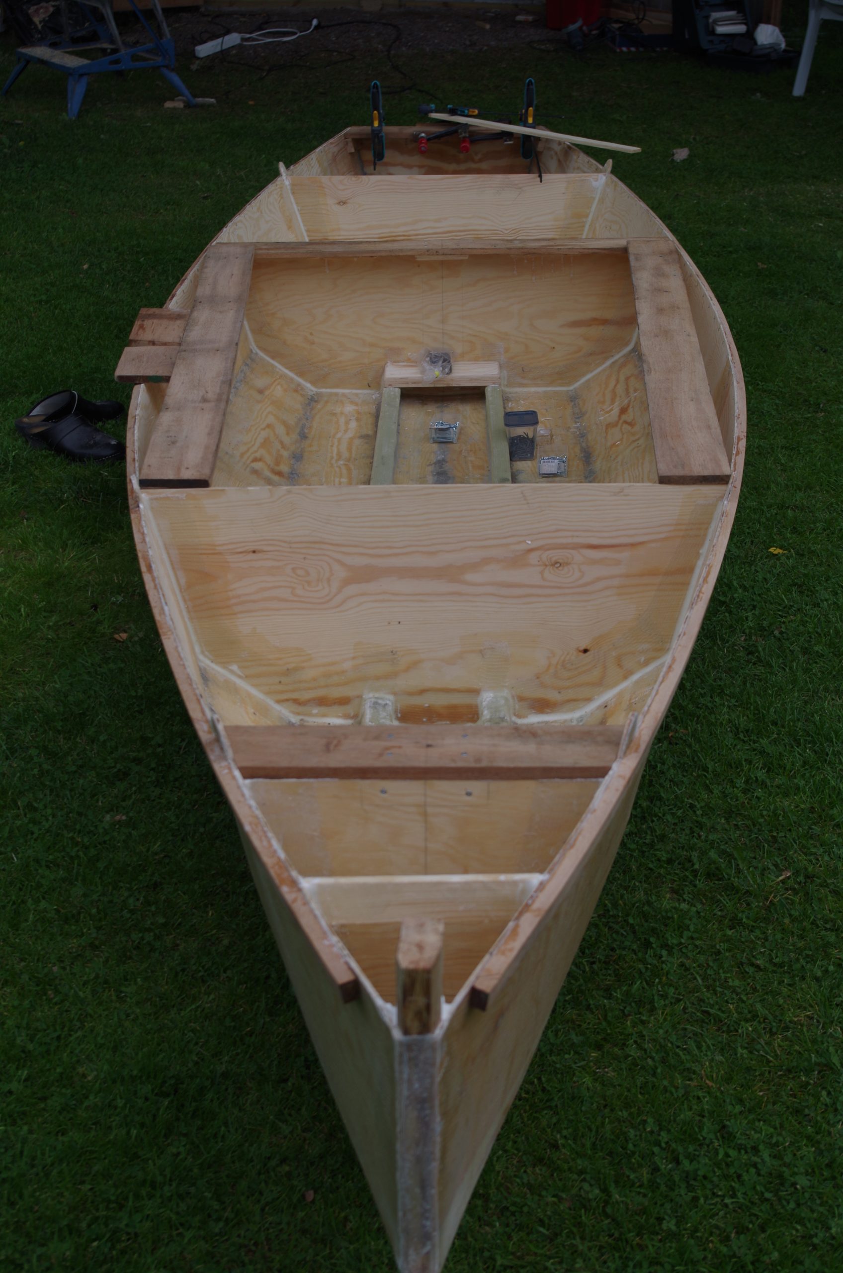
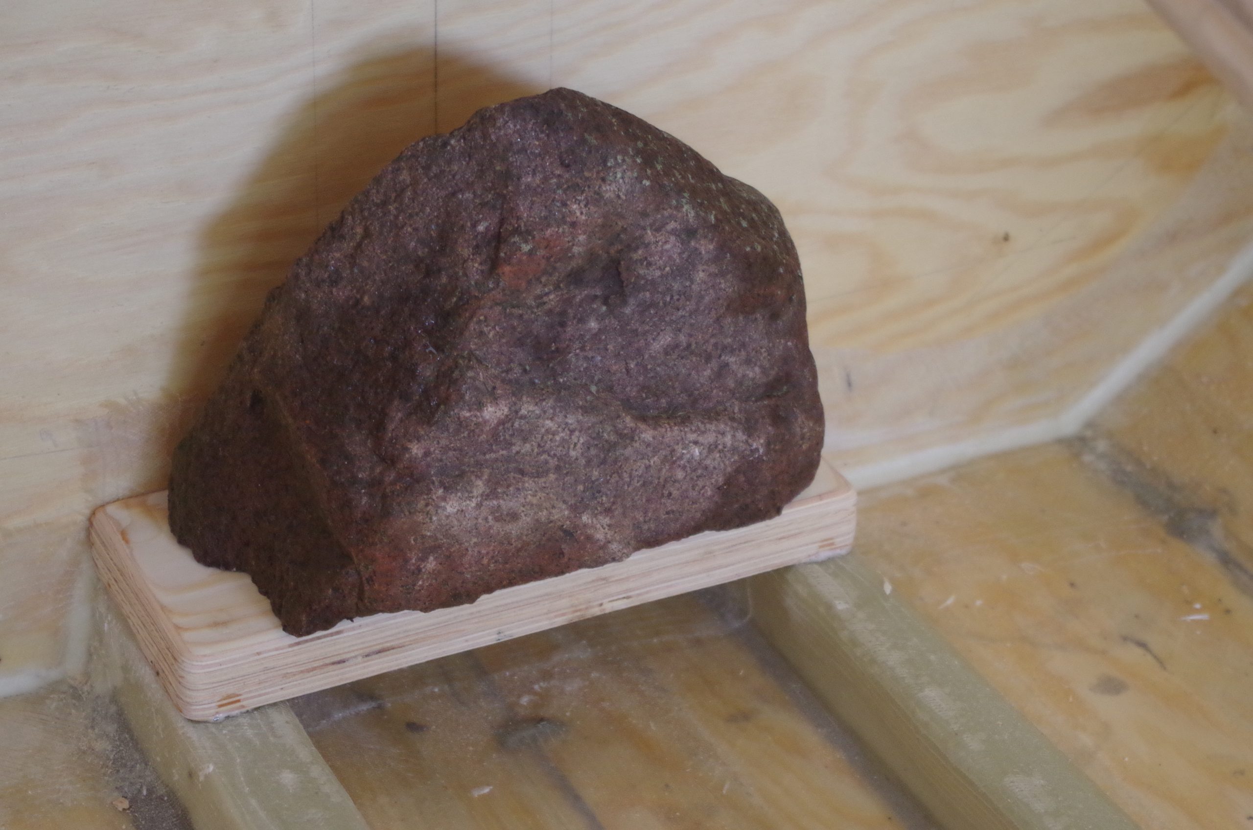
To get a good very solid piece of wood on which to stand the mast, so that brackets and the like could be screwed to something we made a very think piece of plywood from some thinner pieces. We then sawed out blocks and glued them in place where the foot of the mast is supposed to be.
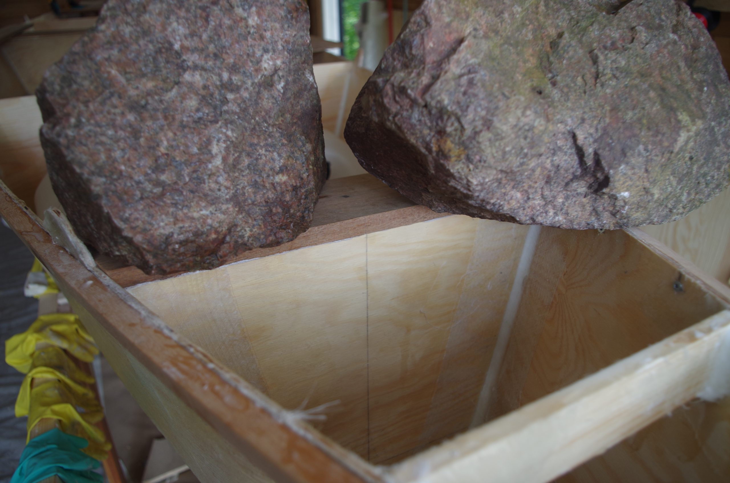
To support the masts sideways we used some of the mahogany to create athwartships planks much like the optimist is designed. The where fastened to the bulkheads as well as to the freeboard using screws and blocks of wood. The stern also got a similar plank to support the structure.
Summer 2020 progress and test paddle
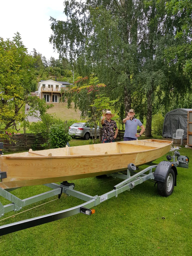
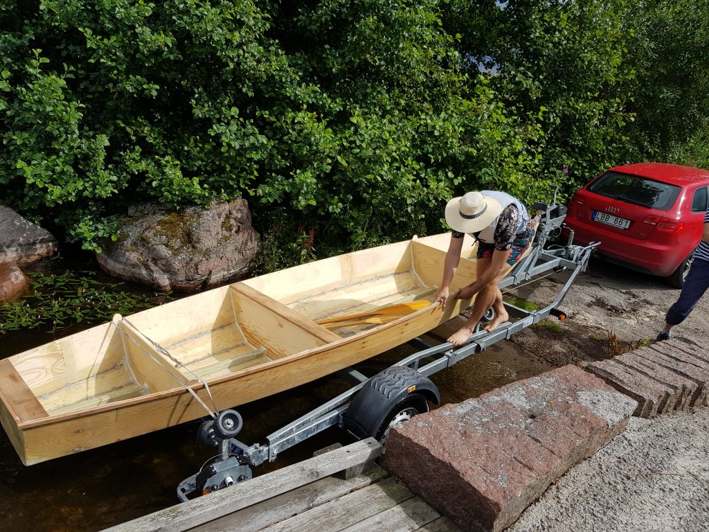
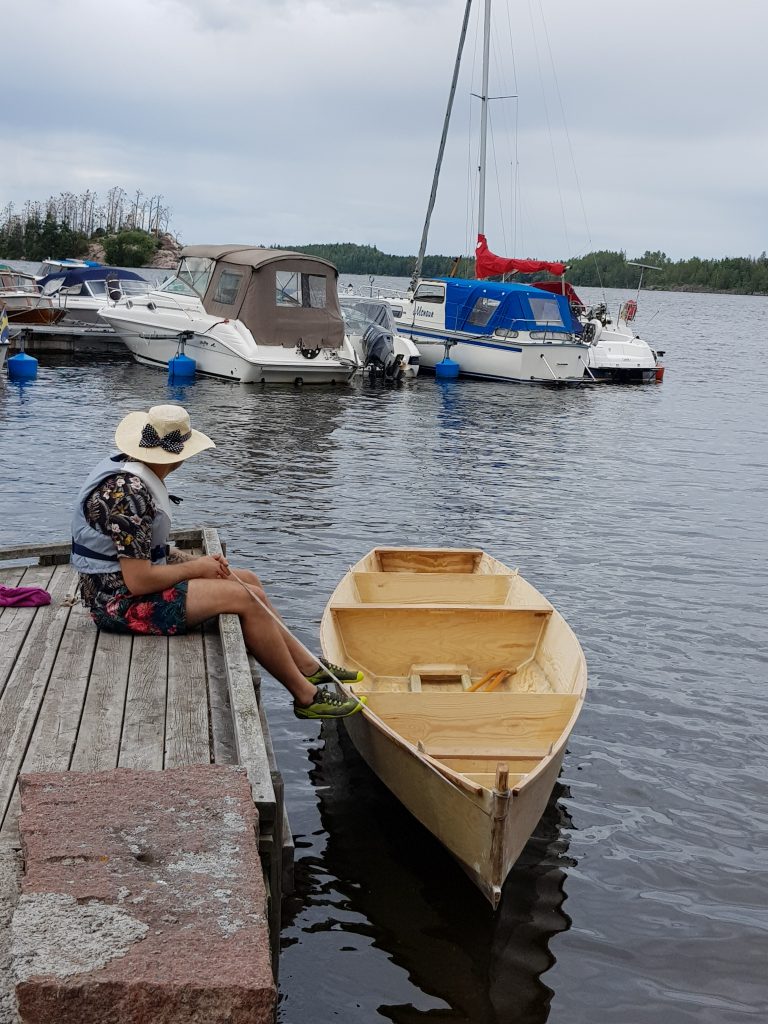
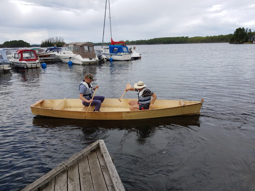
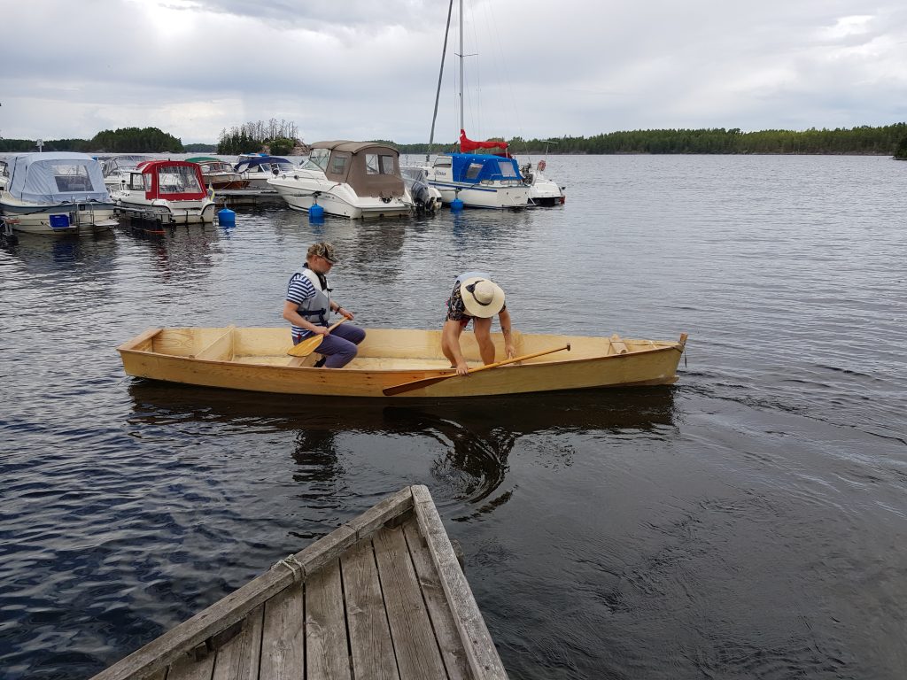
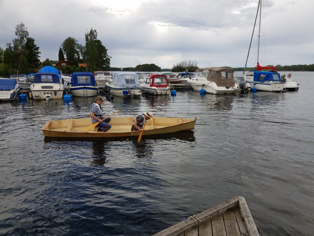
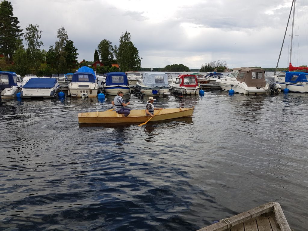
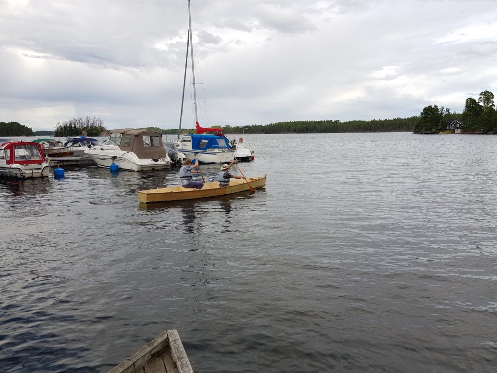
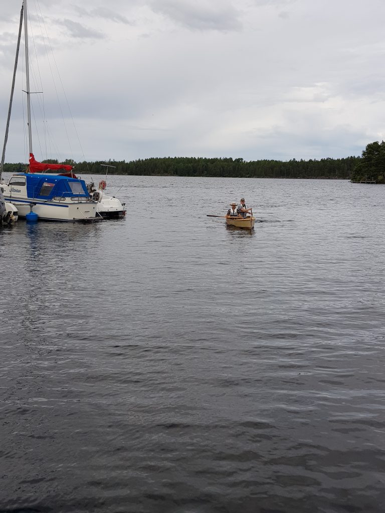
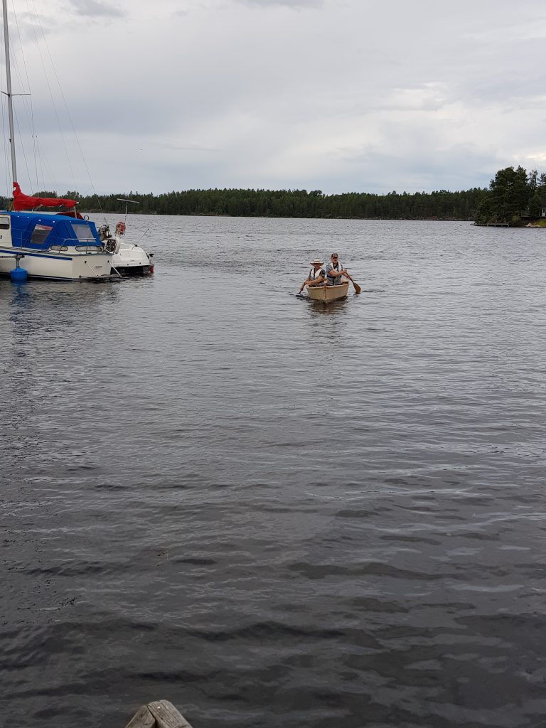
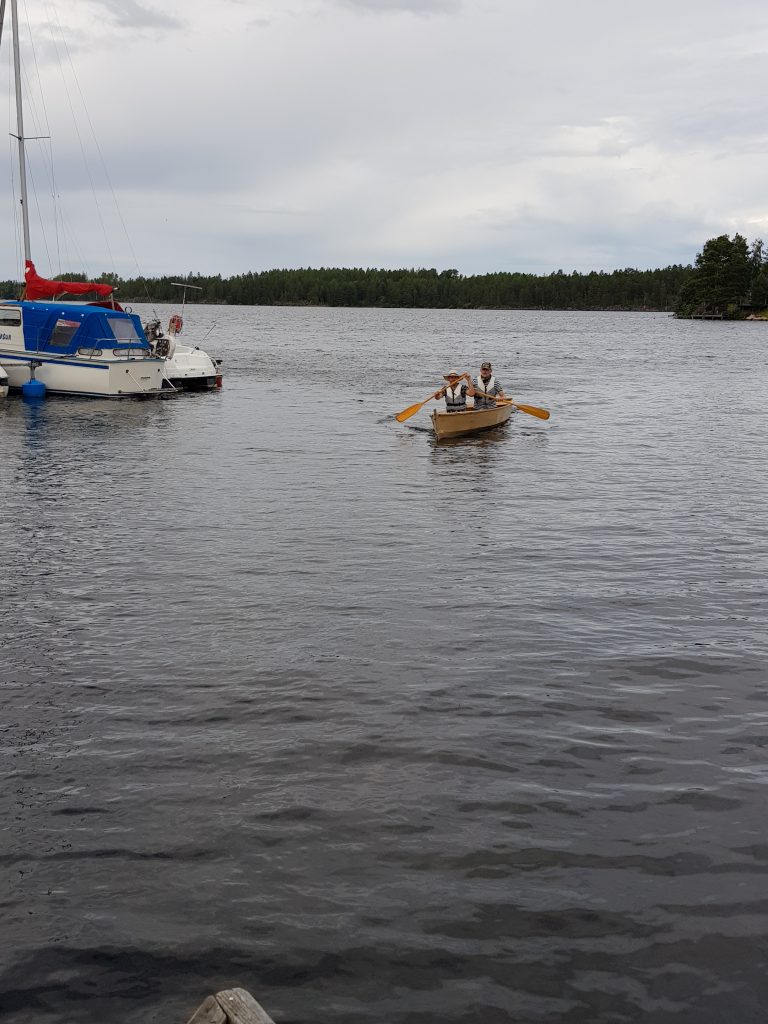
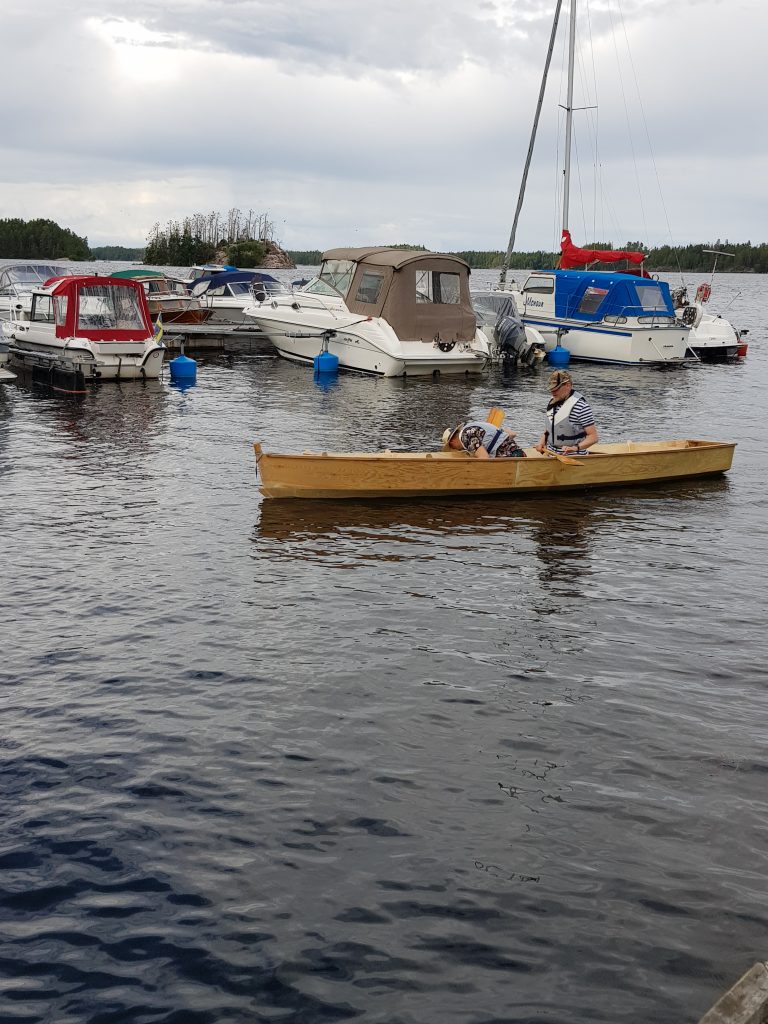
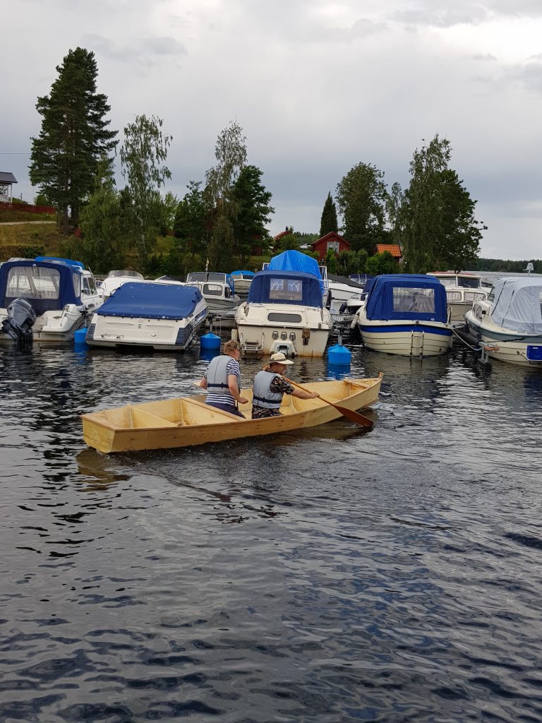
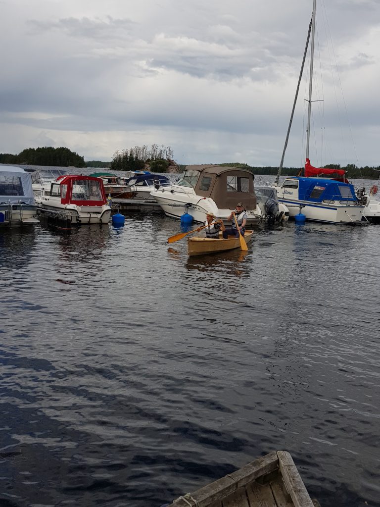
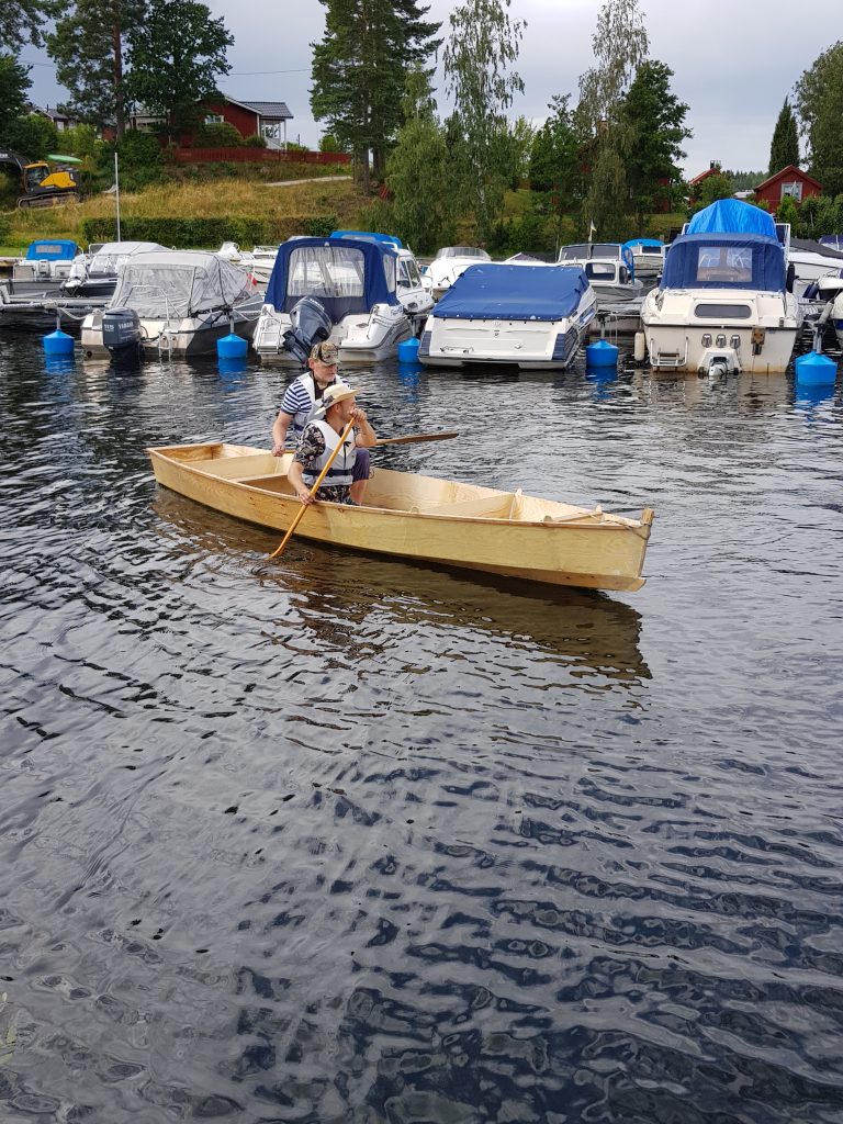
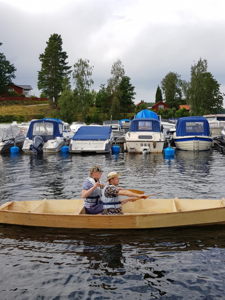
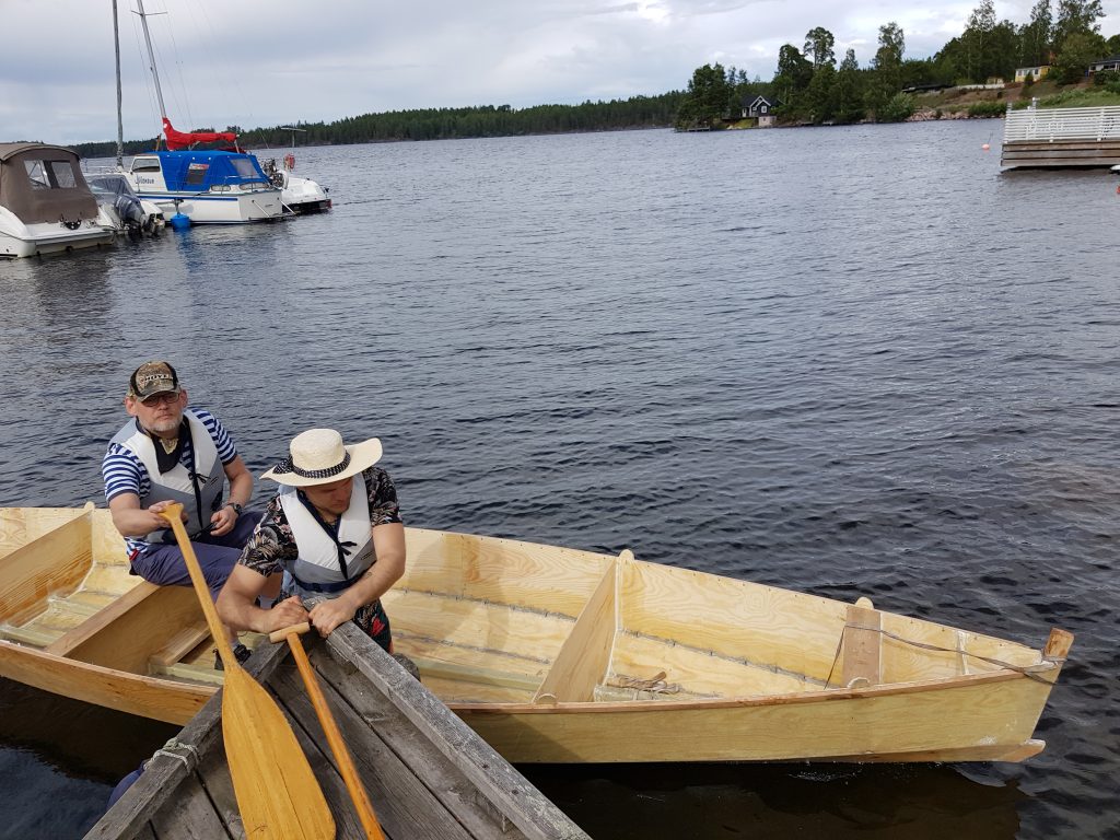
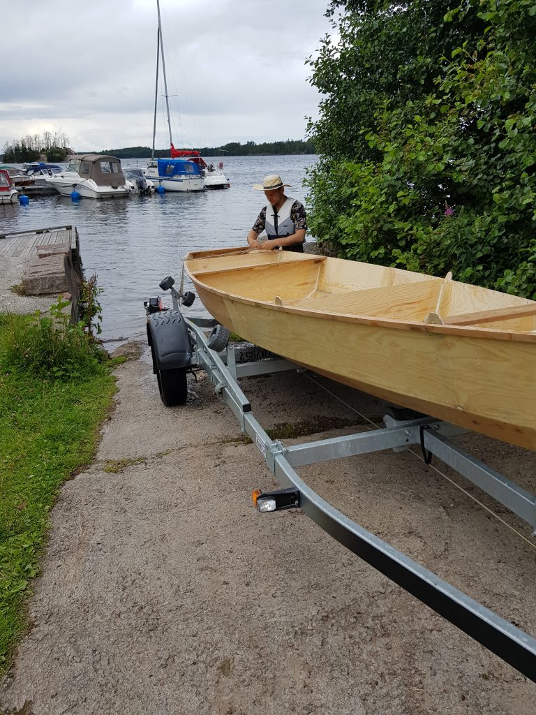
We didn’t get much further this summer, just some further planing of the spars and some studies on how to place the side decks on which one is to sit. We did drag it down to the water and test-paddle it though. It was not directionally stable at all, but it was never designed to be paddled, at the very least not without a rudder. We’ll see what happens when some fins are added.
